Skip to content
Permanent magnet direct drive motor for heavy industrial applications
Permanent magnet direct drive

Direct drive for heavy-duty applications.

MotiraTech engineers and integrates gearless PMDD drive systems for conveyors and continuous-duty industrial equipment — application assessment, specification, retrofit and new-build coordination, commissioning and technical support.

Engineering position

Direct drive is an architecture decision, not a product swap. We assess each application on its duty, mechanical interface and electrical infrastructure, and we say so when a conventional drive-train remains the correct answer.

  • 01Drive
  • 02Torque
  • 03Speed
  • 04Motor
  • 05Conveyor
02What PMDD changes

Remove the gearbox from the equation

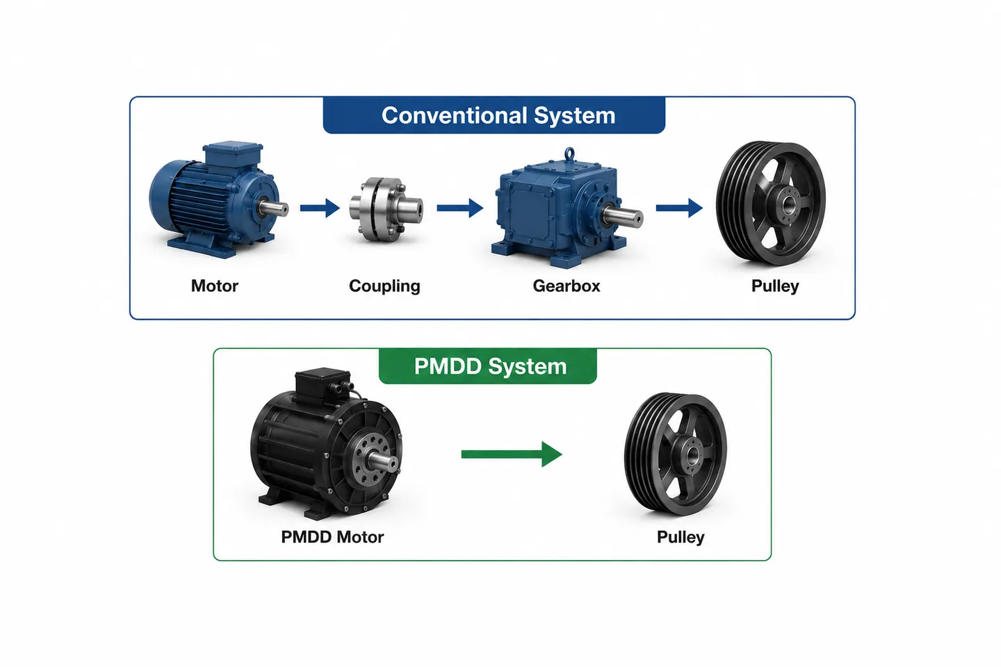
A PMDD system replaces the motor-and-reducer chain with a low-speed, high-torque permanent magnet motor operating under variable-frequency control, coupled directly to the driven shaft.

A — Conventional drivetrain4 elements
  1. Motor
  2. Coupling
  3. Gearbox
  4. Drive pulley

Torque is converted mechanically inside the reducer.

B — Permanent magnet direct drive2 elements
  1. PM motor
  2. Drive pulley
  3. Gearbox
  4. Coupling

Torque is produced at process speed by the machine itself.

Conventional industrial gearbox at a quarry operation
Conventional gearbox arrangement at a quarry operation

Removing the reducer stage removes its couplings, its alignment interfaces and its gear-oil system from the drive path. What remains is a machine that turns at the speed of the driven equipment, controlled electrically rather than geared mechanically.

  • 01No gearbox
  • 02No gear oil
  • 03Reduced mechanical complexity
  • 04Direct torque transmission
  • 05Reduced maintenance exposure
03Engineering principles

How a permanent magnet direct drive works

Four characteristics define the architecture, and each of them changes how the drive is specified, mounted and controlled.

01

Torque produced at process speed

A permanent magnet motor is wound with a high pole count so it develops rated torque at the low rotational speed the driven equipment actually needs. There is no mechanical speed conversion stage between motor and shaft.

Direct drive motor assembly mounted to a conveyor drive shaft
Motor coupled to the conveyor drive shaft
02

Excitation by magnets, not rotor current

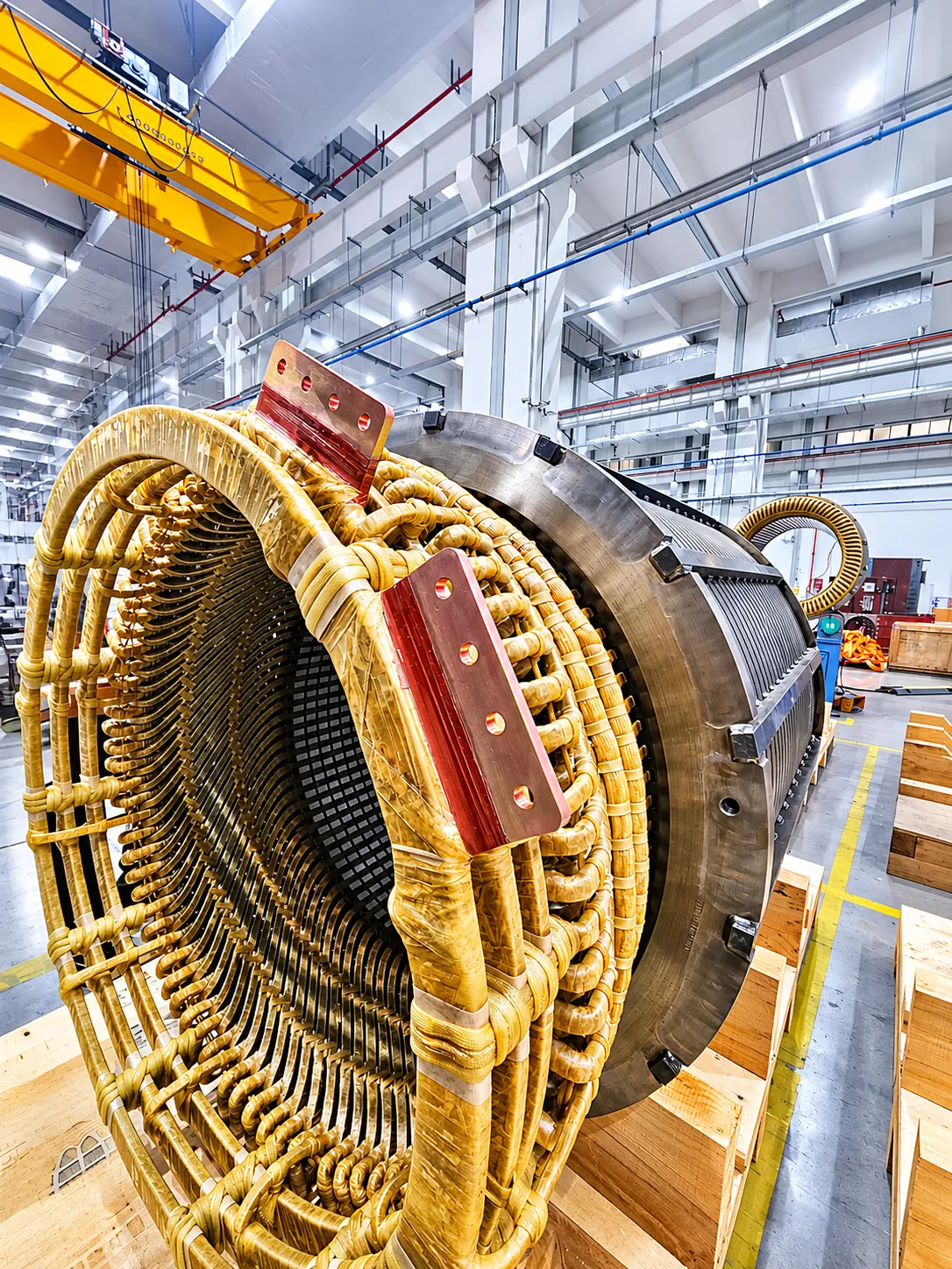
Rotor flux comes from permanent magnets rather than induced rotor current, so the rotor does not rely on slip to produce torque. Machine behaviour and thermal loading therefore differ from an equivalent induction machine.

Large motor stator with copper windings during manufacture
Stator winding during manufacture
03

Speed and torque set by the drive

A PM motor operates under variable-frequency control across its full range. Ramp profiles, torque limits and load sharing between multiple drive units are configured in the drive rather than in mechanical hardware.

Variable-frequency drive cabinets for permanent magnet motor control
Variable-frequency drive cabinets
04

Fewer elements in the torque path

Removing the reducer and its couplings removes their alignment, lubrication and wear interfaces. The trade is a heavier, larger-diameter machine and a stiffer structural and electrical interface to design for.

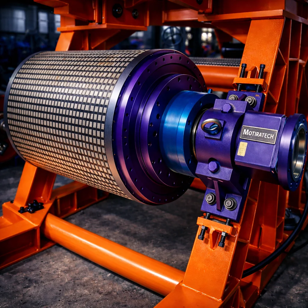
Direct drive conveyor drum pulley assembly with integrated drive housing
Direct drive conveyor drum assembly
04Drive architecture

Where torque conversion happens

The schematic below traces the power path from supply through the drive to the driven shaft, for both architectures. Both are valid; the correct choice depends on the duty, the interface and the site.

FIG. 01 — Power transmission path, schematic comparisonNot to scale
A — CONVENTIONAL MOTOR / GEARBOX DRIVETRAINSupplyMV / LVDrive / starterVFD or DOLInduction motorhigh speedCouplingGear reducerspeed / torque conversionCouplingShaft5 ELEMENTS IN TORQUE PATHB — PERMANENT MAGNET DIRECT DRIVE (PMDD)SupplyMV / LVVFDPM controlLow-speed PM motorhigh torque, no speed conversionShaftGear reducer + couplingsnot present2 ELEMENTS IN TORQUE PATH
Topology schematic. Element counts and arrangement vary with the application; the diagram shows where torque conversion occurs, not rated performance. Direct drive introduces its own structural, mounting and electrical requirements, assessed per application.
Diagram comparing a conventional motor, coupling and gearbox drivetrain with a direct drive system
Comparison graphic from MotiraTech technical material: conventional induction motor with gearbox (above) and permanent magnet direct drive (below)
Outcomes are site-specific

Reducing the number of mechanical elements in the torque path removes their associated wear, alignment and lubrication interfaces. The resulting availability, maintenance and energy outcomes for a given asset are established from its own installation, duty cycle and operating data during application engineering.

05Comparison

Conventional drivetrain vs. direct drive

Only the characteristics that follow from the architecture itself. No performance figures are stated, and direct drive is not the correct answer in every installation.

A — Motor + gearboxConventional
  • 01High-speed induction motor sized for the reducer input, not the driven shaft.
  • 02Gear reducer converts speed to torque; requires lubrication, cooling and oil condition management.
  • 03Couplings, backstops and, in some arrangements, fluid couplings or a jackshaft in the torque path.
  • 04Mechanical alignment must be held between motor, reducer and driven shaft.
  • 05Starting and load-sharing behaviour partly determined by mechanical components.
B — Permanent magnet direct drivePMDD
  • 01Low-speed high-torque permanent magnet motor coupled directly to the driven shaft.
  • 02No gear reducer, therefore no gear-oil system in the drive path.
  • 03Fewer rotating interfaces to align, monitor and maintain.
  • 04Starting, ramp and torque limiting handled by the variable-frequency drive.
  • 05Requires a structural mounting arrangement, torque arm and electrical infrastructure suited to the machine.
Application suitabilitySuitability depends on operating conditions, load profile, speed, torque requirements and site constraints. A conventional drive-train remains the correct answer for a number of applications.
06Applications

Where direct drive is assessed first

Continuous-duty, low-speed, high-torque equipment in mining, bulk handling and heavy industry — where the drive-train governs production availability.

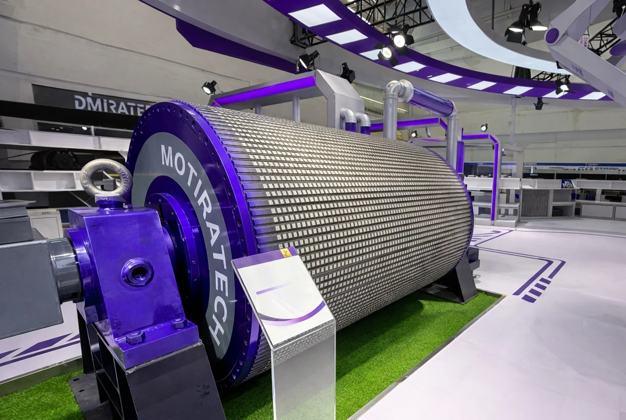
MotiraTech water-cooled permanent magnet drum motor on display
MotiraTech water-cooled permanent magnet drum motor
01Overland and in-plant conveyorsContinuous-duty belt conveyors where drive availability governs throughput and multiple drive units may need coordinated torque sharing.
02Mills and grinding drivesLow-speed, high-torque rotating loads where the drive architecture affects the mechanical and structural design of the installation.
03Crushers, apron feeders and stackersHeavy material-handling equipment with high starting torque and shock-load characteristics that must be defined before drive selection.
04Bulk handling and port terminalsShiploaders, reclaimers and transfer systems where maintenance access and duty cycle shape the drive-train decision.
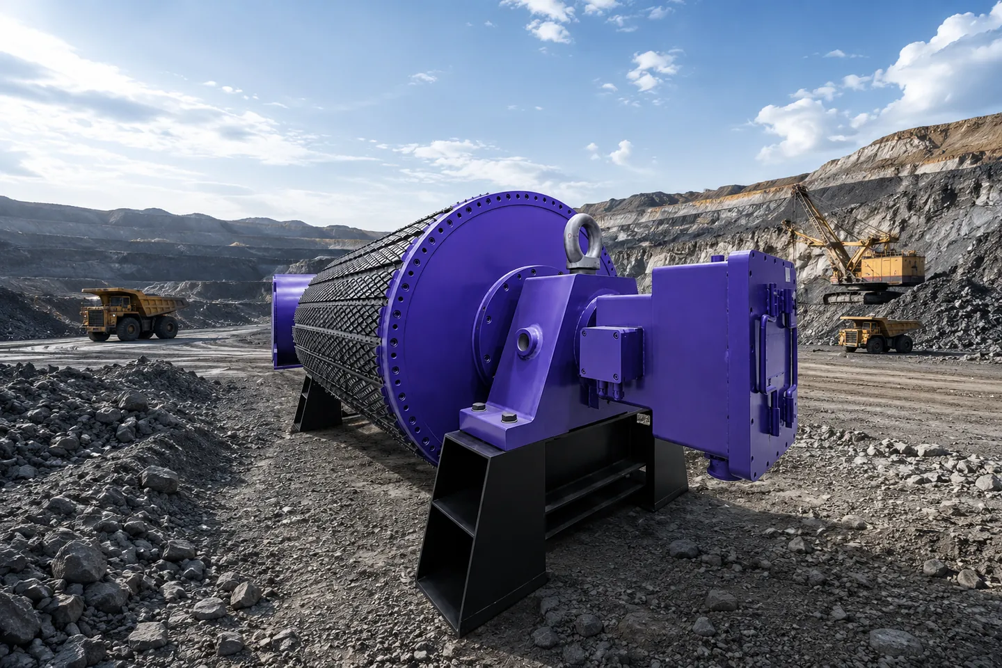
Heavy-duty conveyor pulley for mining and bulk material handling
07Product range

PMDD equipment supplied by MotiraTech

Direct drive motors, integrated drive units and the associated control and power equipment supplied as part of a PMDD package. Ratings, frame sizes and interfaces are selected per application; product data is issued during technical review.

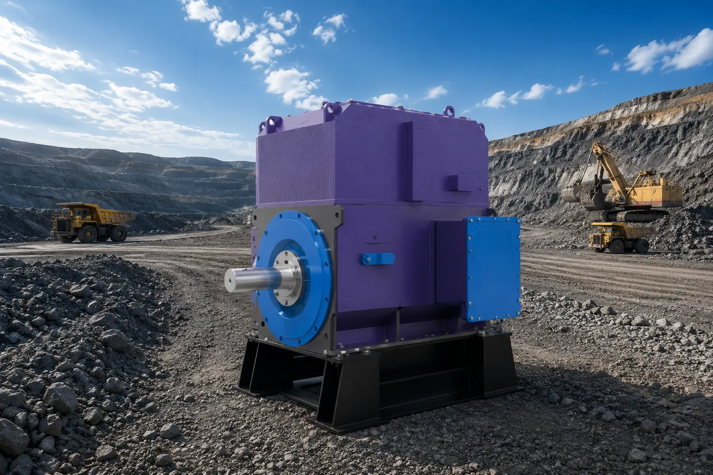
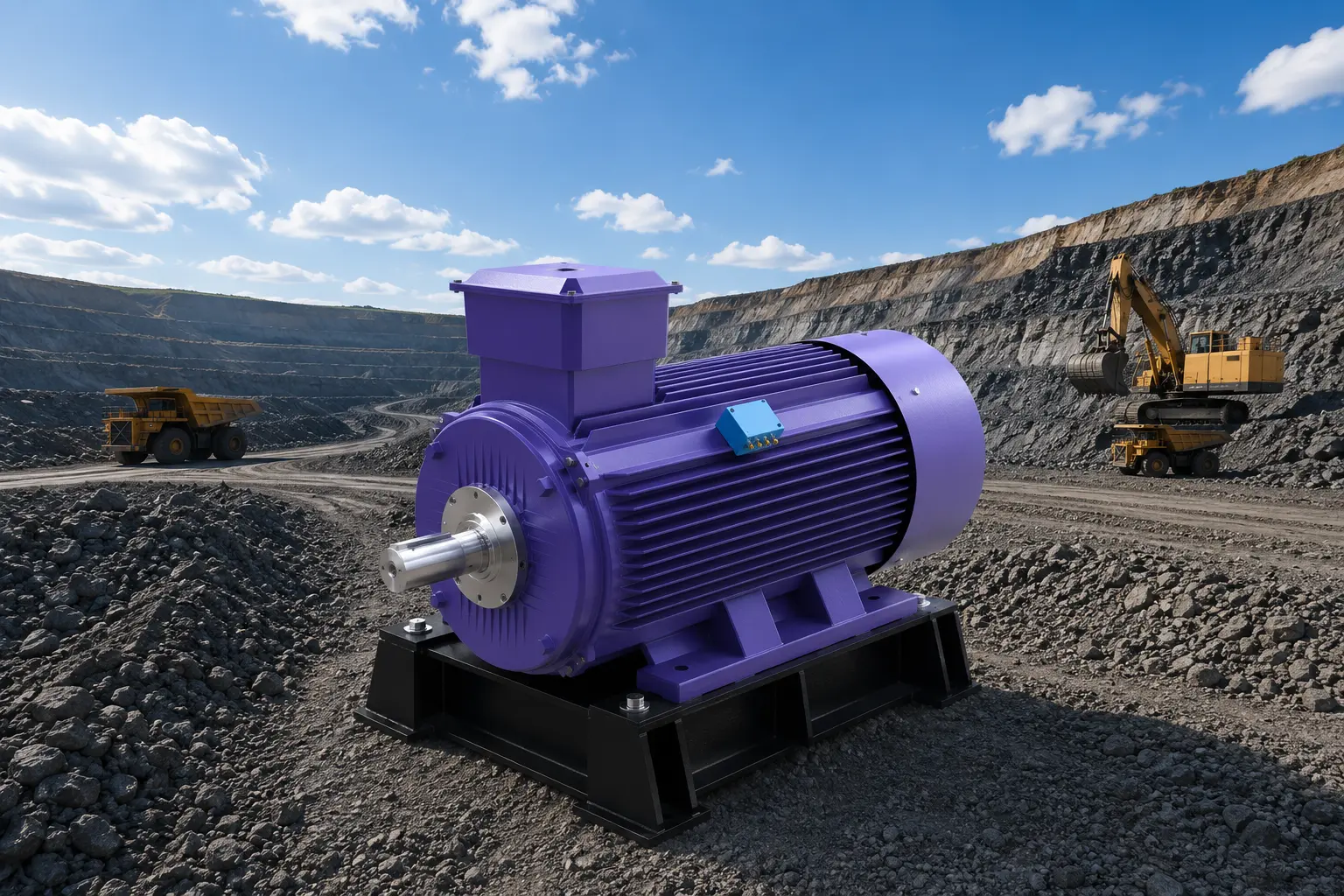
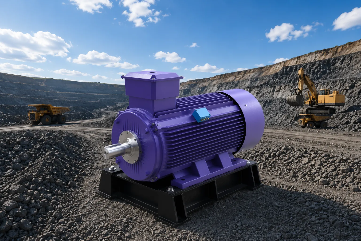
Permanent magnet direct drive motor with ribbed cooling frame on a steel base at a mining site

Ribbed-Frame PMDD Motor

A permanent magnet direct drive motor intended for low-speed, high-torque industrial equipment. The skid-mounted frame supports installation alignment at the drive location.

Core value

Delivers torque directly to the load, reducing the number of mechanical transmission interfaces.

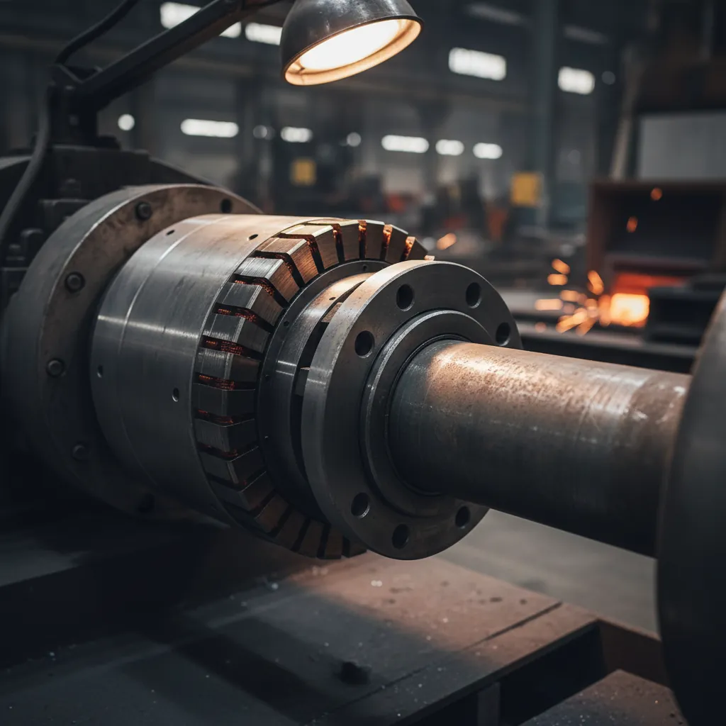
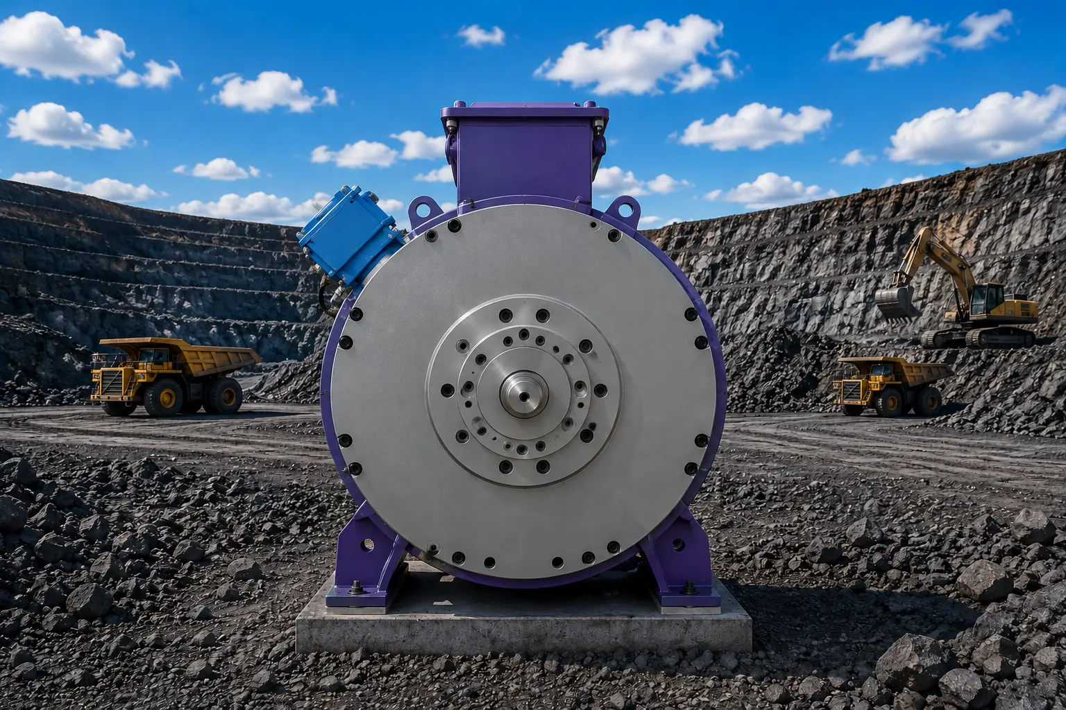
Drive-end flange and output shaft of a permanent magnet direct drive motor

Drive-End Flange Interface

The drive-end arrangement combines the output shaft and mounting flange that connect the motor directly to the driven equipment.

Core value

Provides a direct mechanical interface for the driven shaft, flange and application-specific coupling arrangement.

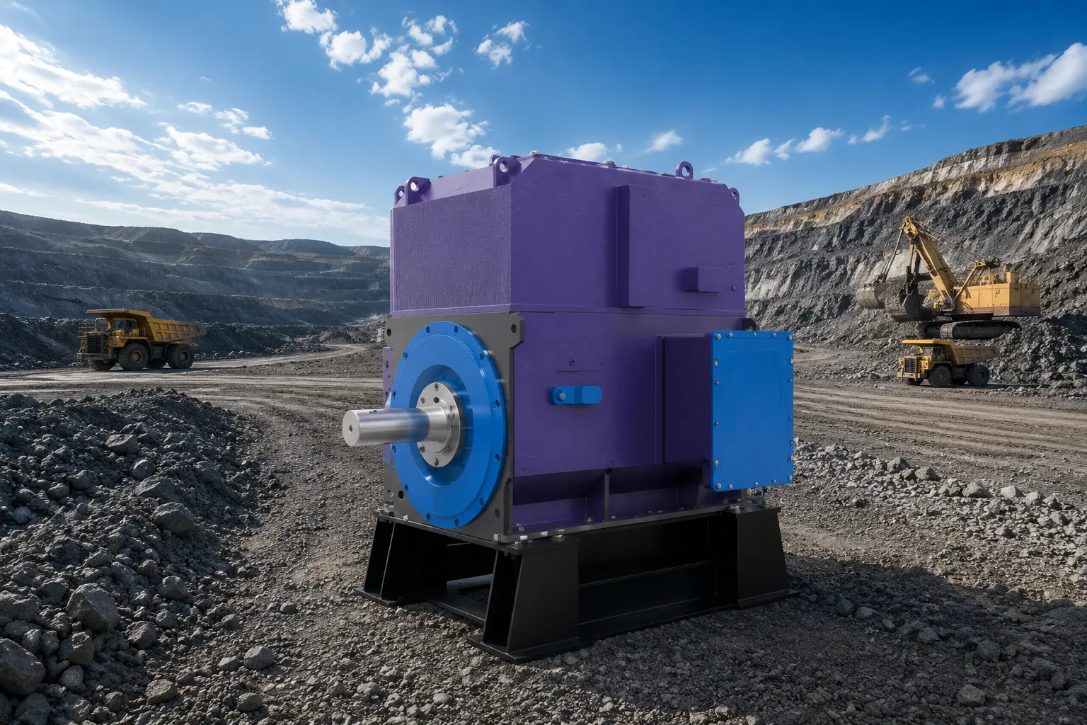
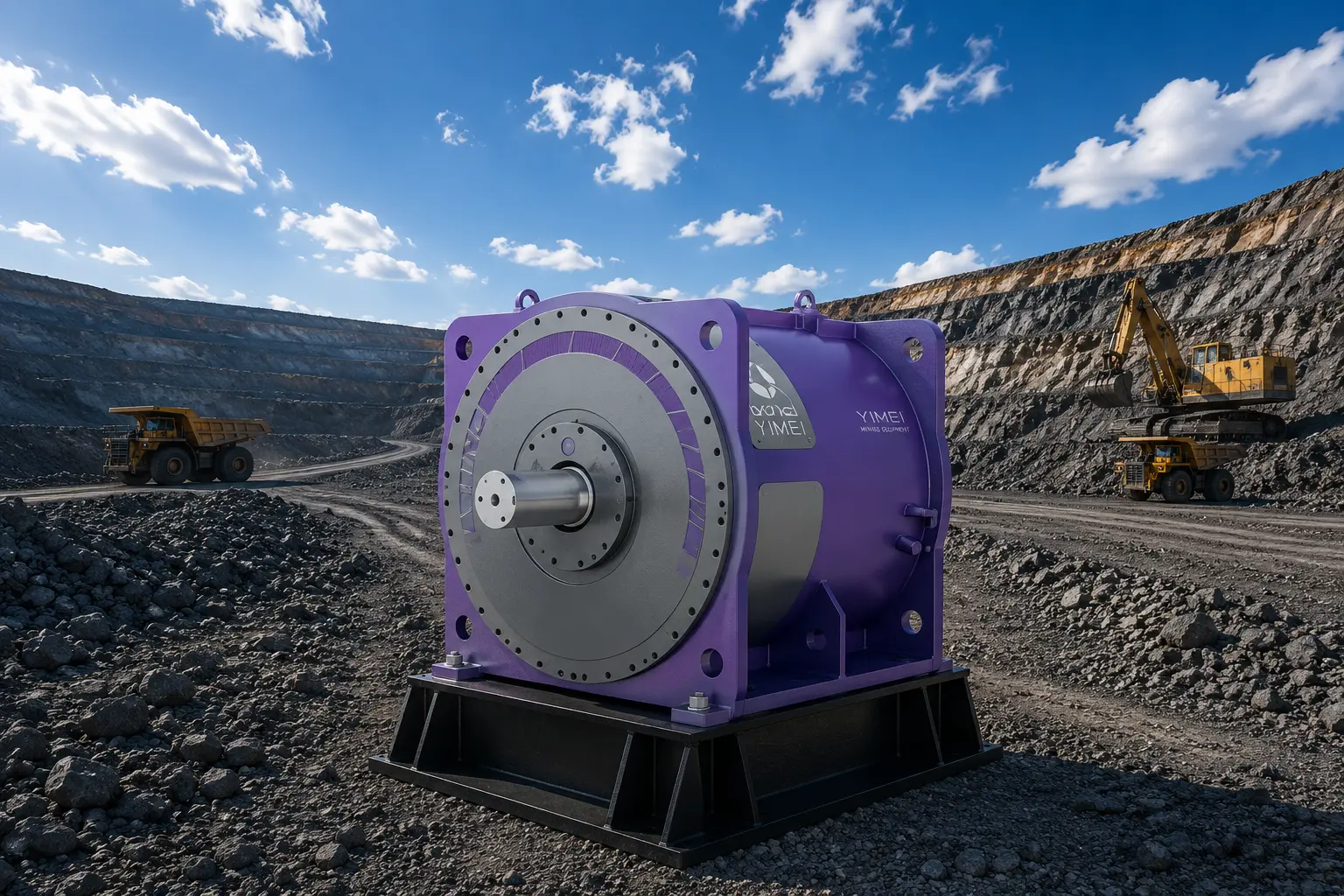
Square-frame low-speed high-torque permanent magnet motor with terminal enclosure

Square-Frame PMDD Motor

A framed permanent magnet motor with an integrated terminal enclosure for connection to the drive and site electrical system.

Core value

Combines the motor, terminal access and mounting envelope in one application-selected drive package.

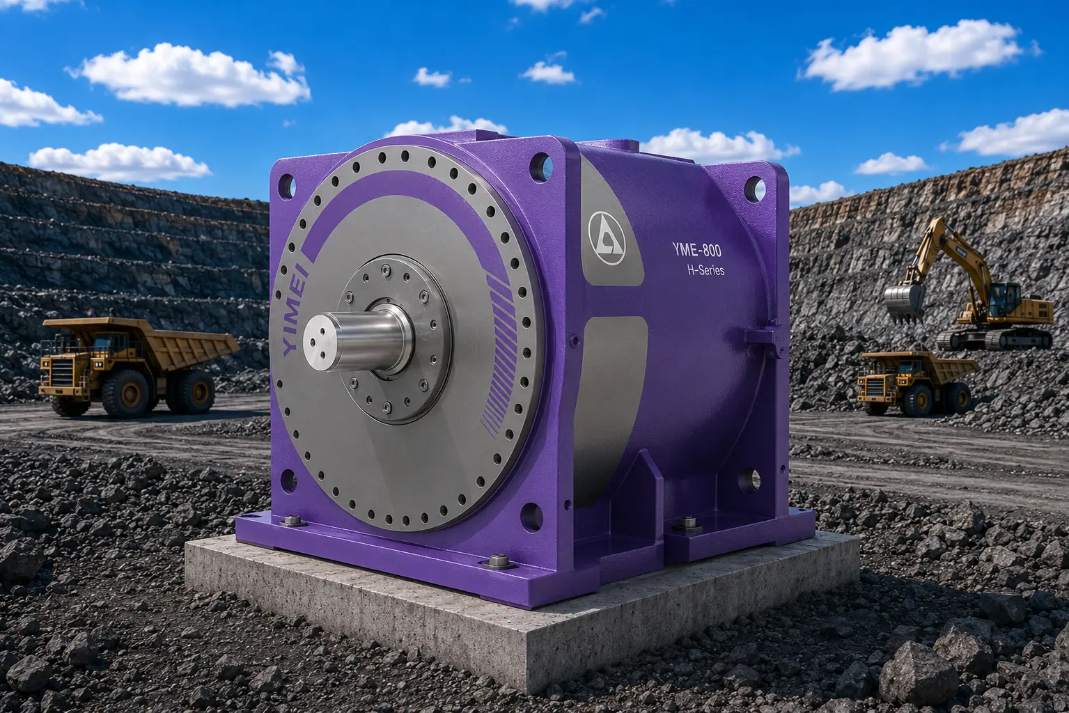
Integrated permanent magnet direct drive unit with flanged output interface

Integrated Direct Drive Unit

A compact drive unit with a flanged output interface, intended for equipment where a coordinated mechanical and electrical package is required.

Core value

Simplifies the drivetrain interface between the permanent magnet motor and the driven equipment.

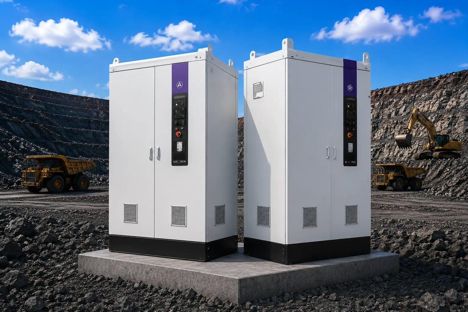
Variable-frequency drive cabinets for permanent magnet motor control

Variable-Frequency Drive Cabinets

Drive cabinets provide the power electronics, protection and control functions required to operate the permanent magnet motor.

Core value

Enables controlled motor starting, speed regulation and integration with the site control system.

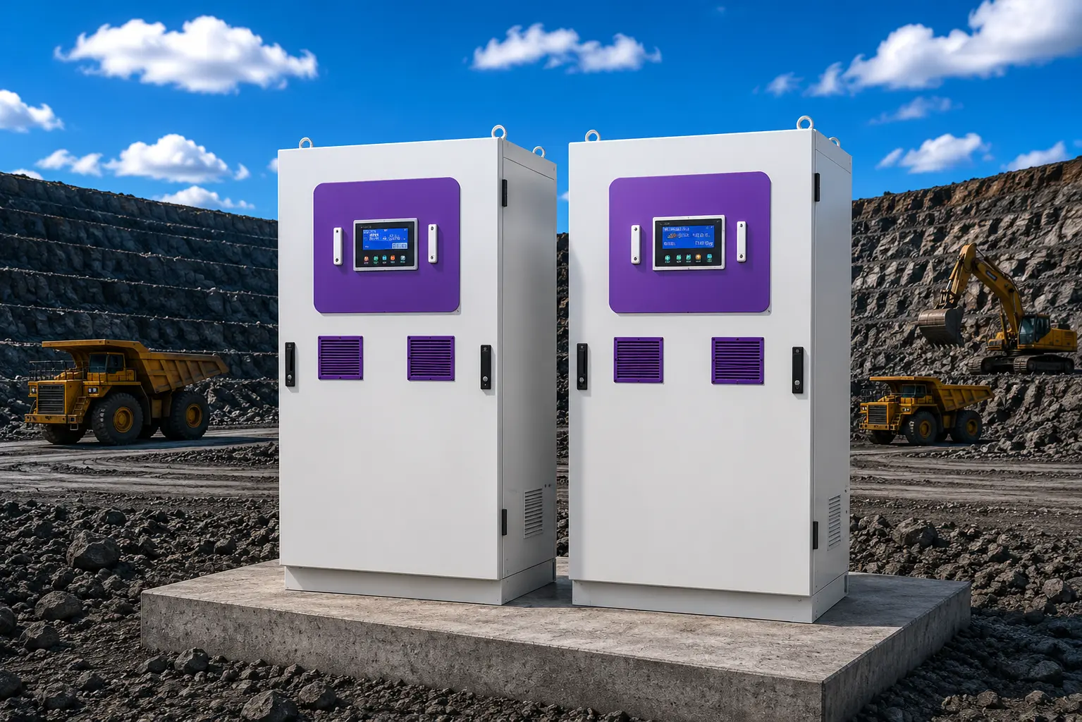
Motor control cabinets with operator HMI panels

Control Cabinets with HMI

Motor control cabinets with operator interfaces for drive supervision, commissioning, status indication and site operating functions.

Core value

Gives operators and commissioning personnel direct access to drive status, controls and operating information.

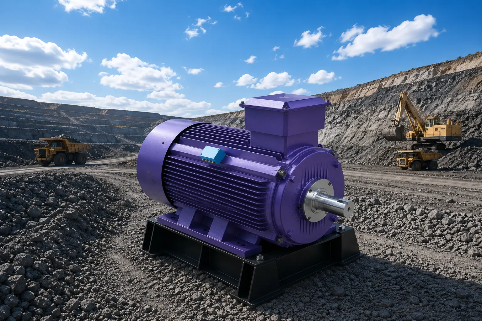
Horizontally mounted permanent magnet motor on a skid base

Horizontal PMDD Motor, Skid-Mounted

A horizontally mounted permanent magnet motor supplied on a fabricated skid base with terminal enclosure and shaft output for connection to the driven equipment.

Core value

Provides a pre-aligned mounting arrangement that simplifies installation at the drive location.

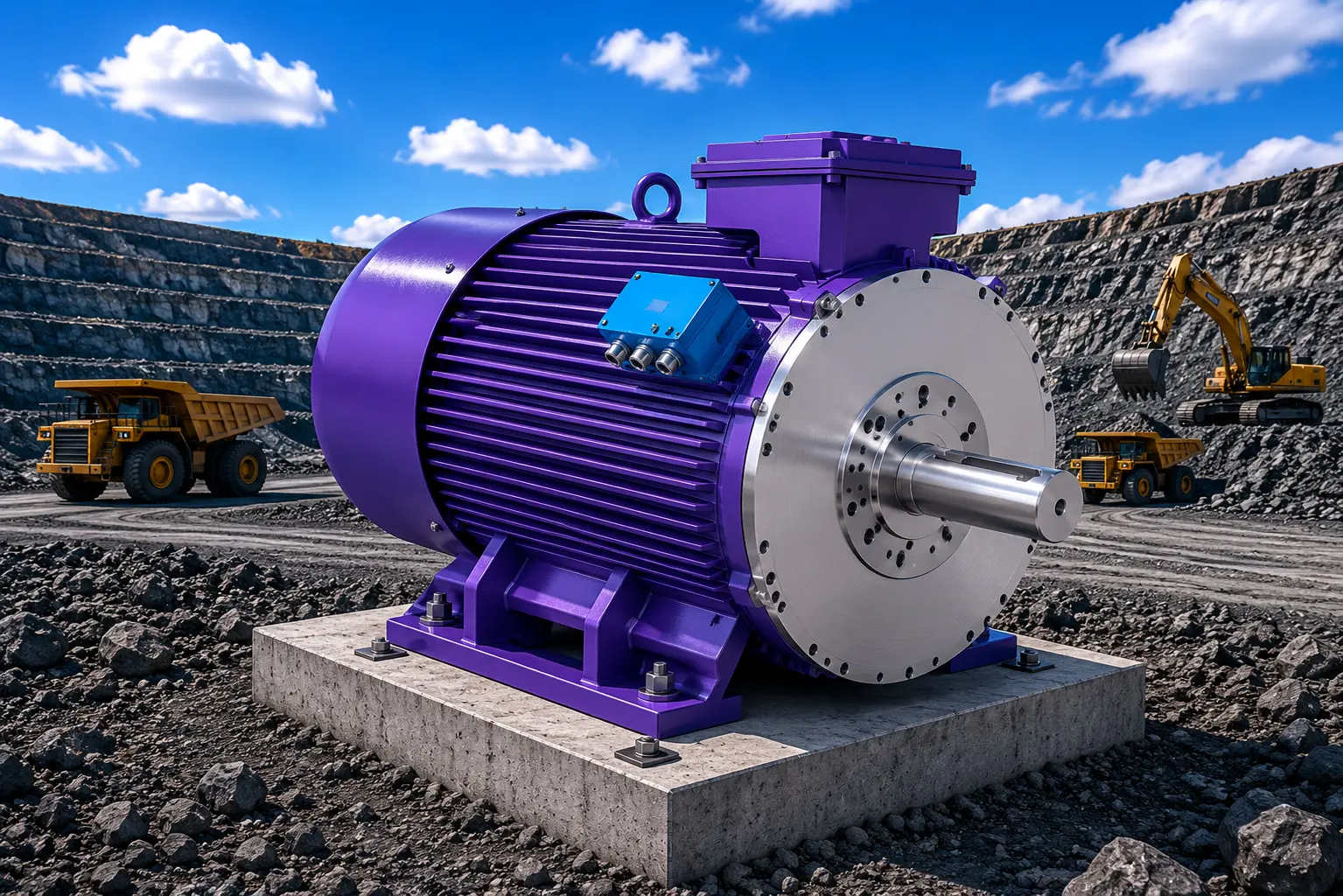
Permanent magnet direct drive motor with output shaft on a concrete foundation

Foundation-Mounted PMDD Motor

A foot-mounted permanent magnet motor installed on a concrete foundation, with drive-end flange, output shaft and separate terminal and instrumentation enclosures.

Core value

Suits fixed-plant installations where the drive is set on a prepared foundation.

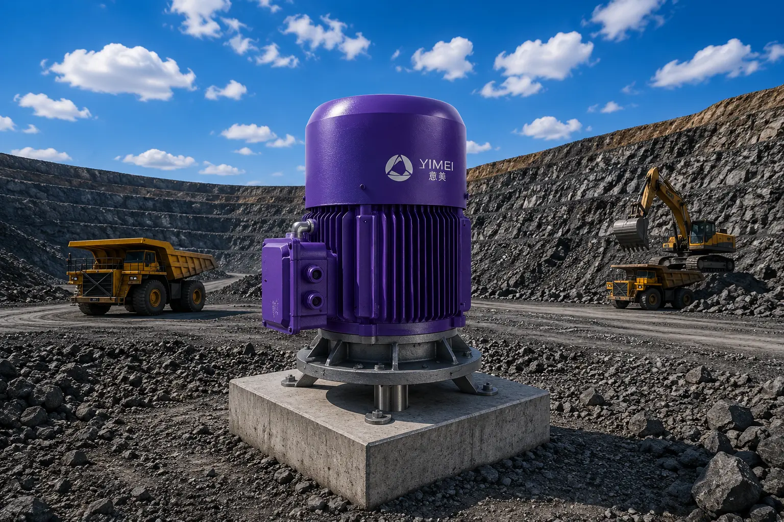
Vertically mounted permanent magnet direct drive motor on a steel base at a mining site

Vertical PMDD Motor Assembly

A vertically arranged direct drive assembly with a downward output shaft, mounted on a structural base for equipment driven from above.

Core value

Supports vertical-shaft equipment without an intermediate right-angle transmission stage.

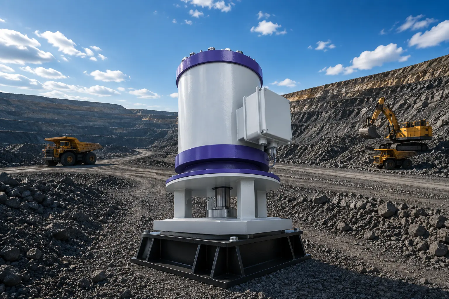
Vertical permanent magnet motor mounted on a pedestal foundation

Vertical Pedestal-Mounted Motor

A vertical permanent magnet motor mounted on a pedestal support with a spider-type mounting frame and side terminal box.

Core value

Keeps the drive footprint compact where floor or platform space is limited.

Direct drive conveyor drum pulley assembly with integrated drive housing

Direct Drive Conveyor Drum

A conveyor pulley with the drive integrated into the drum assembly, combining the lagged drum, bearing arrangement and drive housing in one unit.

Core value

Removes the external gearbox and coupling arrangement from the conveyor drive head.

Square-frame permanent magnet mill drive motor with flanged output

Square-Frame Mill Drive Motor

A large square-frame permanent magnet motor with a flanged drive end, intended for grinding and heavy rotating equipment duties.

Core value

Delivers high torque at mill operating speed through a single direct mechanical interface.

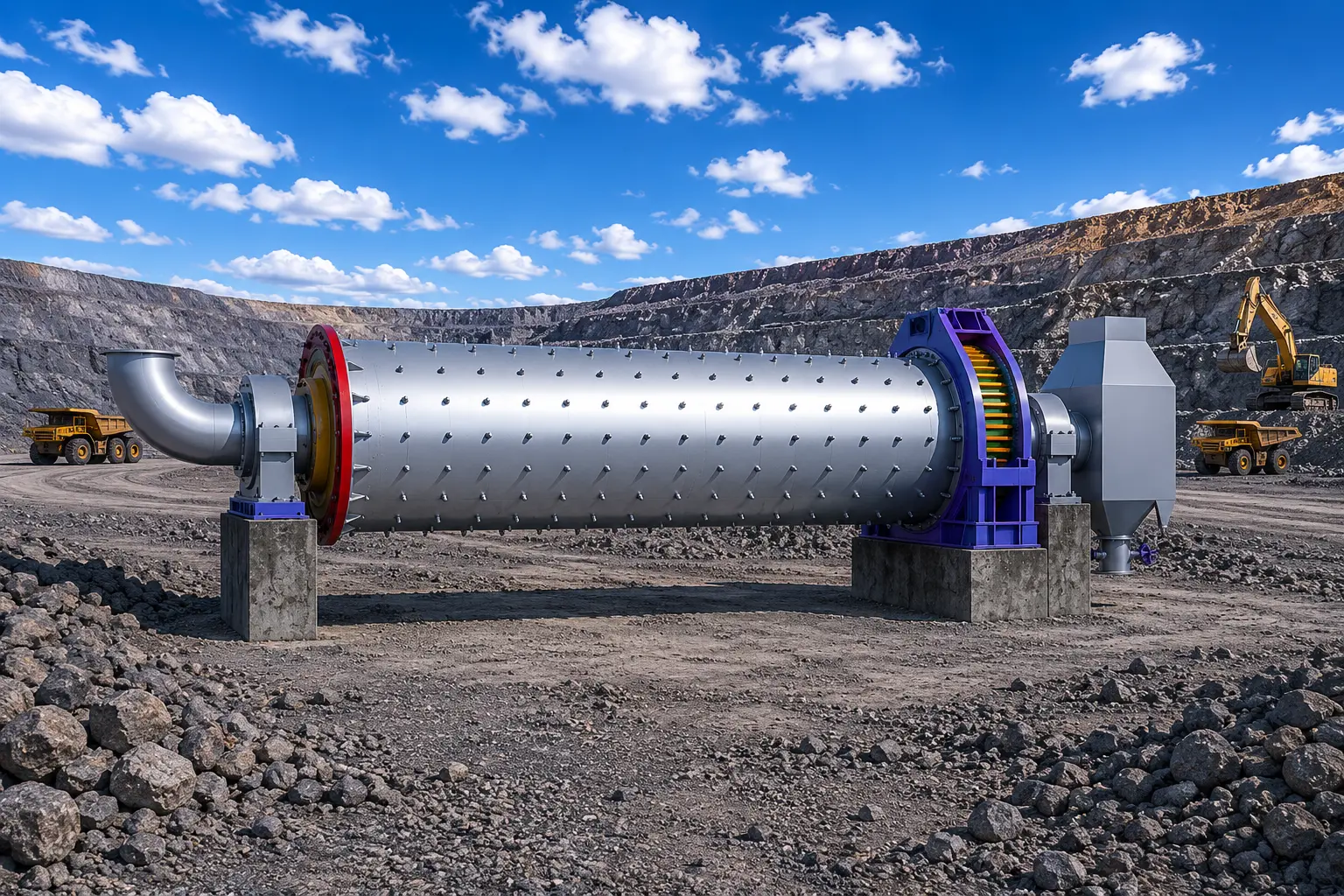
Grinding mill with direct drive arrangement at a mining operation

Grinding Mill Direct Drive Arrangement

A grinding mill shown with a direct drive arrangement at the drive end, illustrating how the motor integrates with the mill trunnion and support structure.

Core value

Shows the installed drive interface used when a mill is converted to or specified with direct drive.

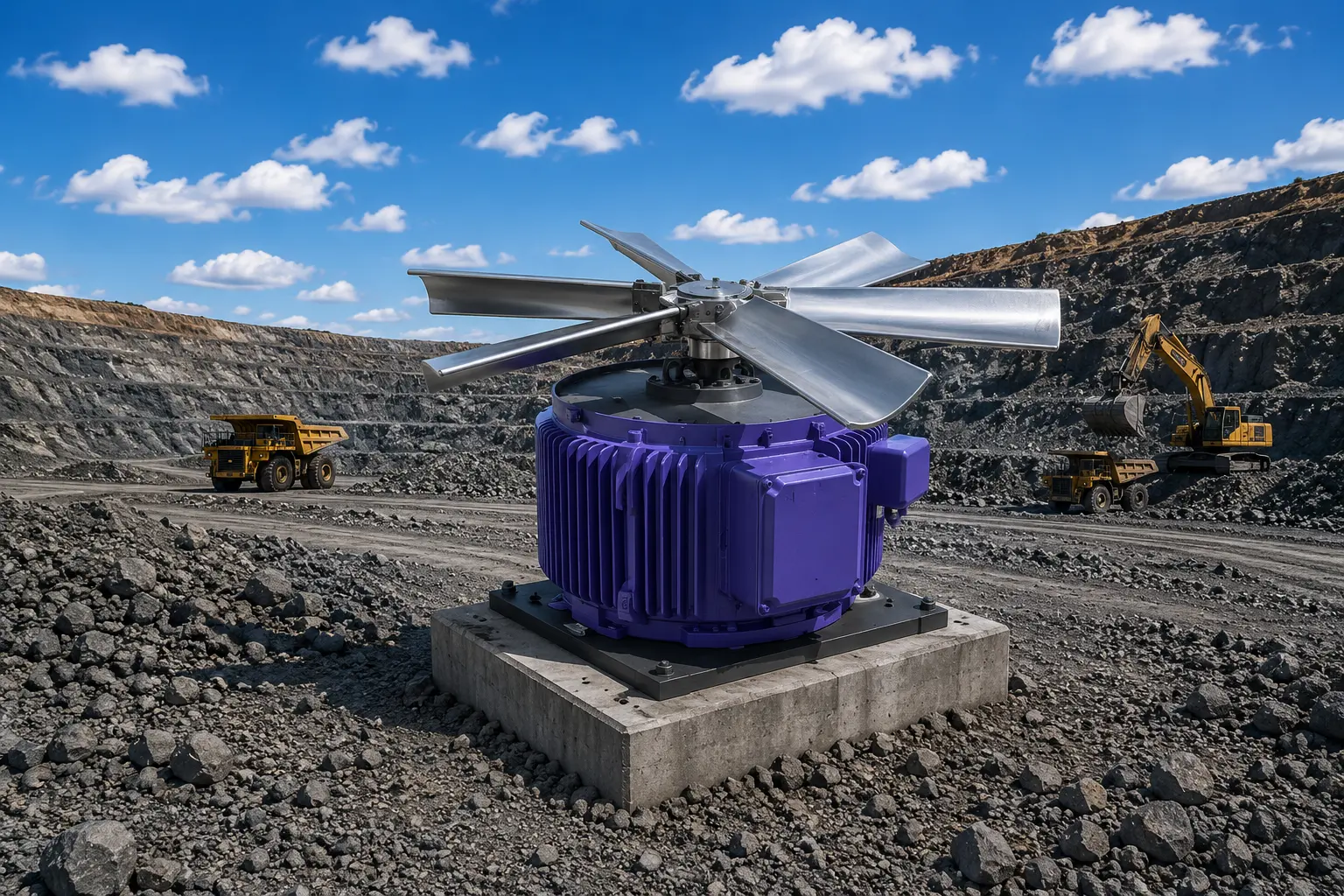
Permanent magnet direct drive motor coupled to an industrial fan impeller

Direct Drive Fan Motor

A permanent magnet motor coupled directly to an industrial fan impeller, arranged for ventilation and air-handling duties.

Core value

Allows fan speed to be set electrically instead of through belts, pulleys or dampers.

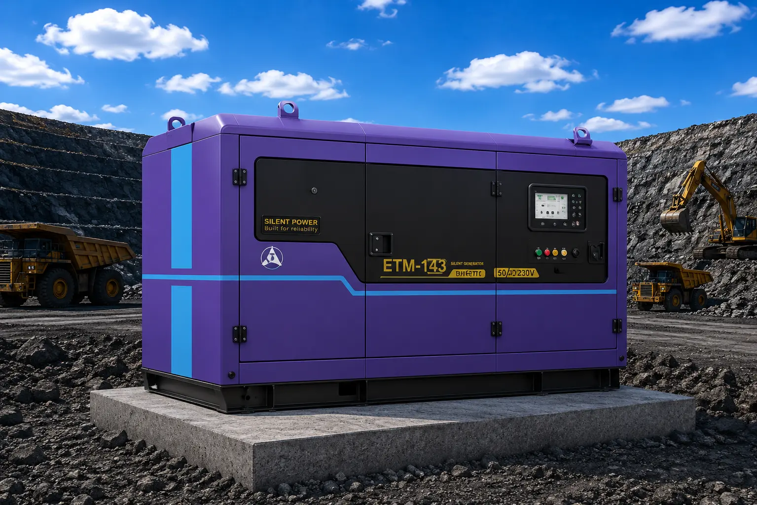
Enclosed generator set for industrial and remote site power

Enclosed Site Power Generator Set

Supporting site power equipment that can be coordinated with a PMDD package for locations requiring local electrical power.

Core value

Supports drive commissioning and operation where site utility power is unavailable or not yet established.

Equipment shown is representative of the PMDD product range. Motor rating, cooling method, enclosure protection, mounting arrangement and drive configuration are confirmed against the application data before any equipment is proposed.

Need product data for a specific duty?

Send the application information and we will issue the matching product documentation.

Request product data
08Technical data

Permanent magnet electric drum pulley series

Published design envelopes for variable-frequency permanent magnet electric drum pulleys. Mining explosion-proof and non-explosion-proof variants exist in each cooling arrangement. Final ratings are confirmed against the conveyor duty.

Water cooled

Water-cooled PM variable-frequency drum pulley

Drum diameter
630–1600 mm
Power range
11–710 kW
Belt speed
1.0–6.3 m/s
Rated voltage
380 / 660 / 1140 V
Explosion protection
Ex d I Mb (mining variant)
Thermal class
180 (H)
Protection
IP55
Mounting / cooling
IM B3 / IC46W
Duty
S1 continuous
Forced air cooled

Air-cooled PM variable-frequency drum pulley

Drum diameter
500–1000 mm
Power range
11–250 kW
Belt speed
1.0–6.3 m/s
Rated voltage
380 / 660 / 1140 V
Explosion protection
Ex d I Mb (mining variant)
Thermal class
180 (F)
Protection
IP55
Mounting / cooling
IM B3 / IC416
Duty
S1 continuous
Self cooled

Self-cooled PM variable-frequency drum pulley

Drum diameter
500–1000 mm
Power range
11–145 kW
Belt speed
1.0–6.3 m/s
Rated voltage
380 / 660 / 1140 V
Explosion protection
Ex d I Mb (mining variant)
Thermal class
155 (F)
Protection
IP55
Mounting / cooling
IM B3 / IC01
Duty
S1 continuous
How to read this dataThese are series envelopes, not a quotation. Drum diameter, rating, belt speed, protection and explosion-protection class are selected per conveyor and confirmed in technical review before anything is proposed.
09Duty ranges

Marine, offshore and process-industry PMDD ranges

Beyond conveyor drives, permanent magnet direct drive machines are built for marine propulsion, shaft generation and continuous process equipment. The ranges below are the published product envelopes for those duties.

Water cooled

Water-cooled PMDD motor

Power range
5–2000 kW
Voltage range
380–690 V
Speed range
0–1500 rpm
Protection
≥ IP56
Insulation
H / F
Ambient
−20 °C to +55 °C
Duty
S1 continuous
Forced air cooled

Air-cooled PMDD motor

Power range
5–1500 kW
Voltage range
380–690 V
Speed range
0–1500 rpm
Protection
≥ IP56
Insulation
H / F
Ambient
−20 °C to +55 °C
Duty
S1 continuous
Water cooled

Segmented (split-type) shaft generator

Power range
400–4000 kW
Rated voltage
690 V
Speed range
45–105 rpm
Protection
≥ IP23
Insulation
H / F
Ambient
−20 °C to +55 °C
Duty
S1 continuous

Marine type approval

Permanent magnet synchronous motors in this range hold China Classification Society (CCS) type approval for shipboard service, covering main propulsion motors and deck machinery motors.

  • 01250–900 kW
  • 021000 / 1500 rpm
  • 03Water cooled
  • 04Insulation F / H
  • 05CCS type approval

Certification is held by the equipment manufacturer. MotiraTech does not issue classification-society approvals; certificate scope is verified per project.

Process equipment served by direct drive

In pulp, paper and comparable process plants, permanent magnet direct drive replaces motor-and-reducer sets on continuous rotating equipment.

  • Impurity separators
  • Broke pulpers
  • Process pumps
  • Cooling tower fans
  • Centrifugal fans
  • Pressure screens
  • Pulp refiners
  • Vacuum systems
  • Dryer cylinders
  • Dryer stabilizer and spreader rolls
Documented retrofit measurementOn a documented 220 m, 600 t/h mineral-processing conveyor (1000 mm belt, 1.6 m/s, Φ800 drive pulley, 75 kW), replacing the motor, reducer and coupling with a permanent magnet electric drum raised measured drive-train efficiency from 0.71 to 0.97 and reduced annual consumption by roughly 80,900 kWh at 330 days × 20 hours and a 0.72 load factor. These are the equipment supplier's measured figures for that installation and are not a performance guarantee for other conveyors.
10Project pathways

Retrofit and new-build applications

Both routes are supported. The engineering effort sits in different places.

Pathway A

Retrofit — existing conveyor or drive

Replacing an existing motor-and-reducer arrangement on an installed asset. The constraint is the existing structure, shaft interface, electrical capacity and the available shutdown window.

  1. 01Survey of the existing drive-train, structure and electrical infrastructure.
  2. 02Confirmation of actual duty from operating data rather than nameplate assumptions.
  3. 03Mechanical interface design: shaft connection, torque arm and base modifications.
  4. 04Electrical scope: drive rating, transformer and cable assessment, control integration.
  5. 05Shutdown planning so removal and installation fit the available outage window.
Pathway B

New build — drive designed in

Specifying direct drive from the design stage, where the structure, electrical infrastructure and control philosophy can be built around the drive rather than adapted to it.

  1. 01Drive architecture evaluated at the concept stage with the equipment supplier.
  2. 02Motor, drive and structure specified as one interface rather than assembled after the fact.
  3. 03Coordination of the electrical room, cabling and cooling with the overall plant design.
  4. 04Control and load-sharing philosophy agreed with the plant control system designer.
  5. 05Factory testing, site installation and commissioning scheduled into the project programme.
Final suitability for either pathway depends on site and equipment conditions, confirmed during application engineering.
11Application data

Information required to evaluate a PMDD application

Send what is available. A first technical position can usually be formed from duty, shaft data and the existing drive arrangement; the remainder is needed before a firm scope or quotation.

01Equipment type & dutyConveyor, mill, crusher, feeder; continuous, intermittent or reversing.
02Shaft power & torqueAbsorbed and installed power, rated and breakaway torque at the driven shaft.
03Driven shaft speedOperating speed range in rpm, plus any creep or inching requirement.
04Existing drive-trainMotor rating and frame, reducer ratio and make, coupling and backstop arrangement.
05Mechanical interfaceShaft diameter and geometry, pulley/trunnion details, available envelope and torque-arm anchorage.
06Structural detailsDrive base or gantry arrangement, drawings, and permitted static and dynamic loads.
07Electrical supplyAvailable voltage, fault level, transformer capacity, cable routes and drive room location.
08Control & protectionExisting PLC/DCS, network protocol, load-sharing scheme, protection and monitoring philosophy.
09EnvironmentIndoor/outdoor, altitude, ambient range, dust, corrosion and hazardous-area classification if applicable.
10Operating profileHours per year, start frequency, loaded starts, seasonal variation, planned shutdown windows.
11Site & logisticsAccess, lifting capability, transport limits and available shutdown duration for installation.
12Project basisRetrofit or new build, target dates, spares philosophy and support expectations.

Have the drawings and duty data?

Our engineering team will review the data and respond with a technical position on suitability and scope.

Send application details
12Engineering & delivery

From assessment to field support

One engineering team carries the PMDD application from technical review through commissioning and ongoing support.

  1. 01

    Application assessment

    Review of duty, load data and site constraints to establish whether direct drive is technically appropriate for the asset.

  2. 02

    Engineering & specification

    Motor and drive specification, mechanical interface concept, electrical scope definition and interface documentation.

  3. 03

    Supply coordination

    Manufacturing coordination, factory testing witness, documentation control and delivery to site.

  4. 04

    Installation support

    Installation method, alignment and mounting support, and coordination with the site mechanical and electrical crews.

  5. 05

    Commissioning

    Drive parameterisation, protection settings, load testing, torque-sharing setup and handover documentation.

  6. 06

    Technical support

    Post-commissioning support, spares planning, condition-monitoring advice and remote or on-site field assistance.


Typically within MotiraTech scope
  • PMDD application assessment and technical feasibility review
  • Motor and variable-frequency drive specification
  • Mechanical interface and torque-arm concept engineering
  • Electrical and control integration scope definition
  • Manufacturing coordination and supply of the drive package
  • Installation supervision, commissioning and setup
  • Documentation, spares planning and ongoing technical support
Typically outside scope unless separately agreed
  • Civil and structural construction works
  • Site electrical installation labour and cable pulling
  • Plant-wide process design and equipment supply beyond the drive package
  • Statutory approvals and permitting

Motor ratings, torque and speed envelopes, enclosure and cooling arrangements, environmental limits and any third-party certification are confirmed per application against manufacturer documentation. No product data sheets or certification claims are published on this page, and none are implied.

PMDD

Have an existing conveyor or drive application?

Send us the operating and equipment information. Our team can review the application and determine whether a PMDD architecture is appropriate.