
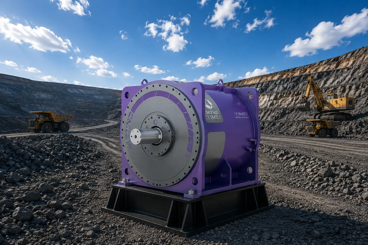
Direct Drive Systems for Cement & Aggregates Plants
Permanent magnet direct drive for the equipment that carries a plant's continuous duty — conveyors, elevators, separators, mills, clinker cooler and process fans, cooling towers and vertical mills — with site assessment, integration and commissioning support.
Where drives carry the load in a cement plant
Cement production is continuous and energy-intensive: material handling, grinding, pyroprocessing and separation all depend on rotating equipment that must run between planned outages. Drive selection in these stages is an availability decision as much as an efficiency decision.
- 01
Quarry & raw material handling
Belt conveyors, chain (slot) conveyors and bucket elevators move limestone, clinker, slag, ash and aggregate continuously between stages, often in dusty and abrasive conditions.
- 02
Raw grinding
Ball mills and vertical roller mills carry the plant's largest drive loads, running long campaigns where drivetrain availability governs plant output.
- 03
Pyroprocessing
Kiln line auxiliaries, clinker cooler fans and process fans define a large part of plant electrical demand and respond directly to speed control.
- 04
Finish grinding & separation
Separators and classifiers set product fineness. Precise, stable speed control on the separator drive is a quality parameter, not only an energy parameter.
- 05
Waste heat recovery & cooling
Cooling tower fans in the waste heat power generation loop run at low speed and high torque, where geared fan drives are a recurring maintenance item.
Where permanent magnet direct drive is applied
A permanent magnet motor wound for the driven speed removes the reducer, high-speed coupling and its lubrication system from the drivetrain. In a cement plant that matters most where duty is continuous, torque rather than speed defines the machine, and the drive is difficult or costly to service. It is an application decision, not a blanket replacement for every geared drive on site.
What a plant drive evaluation requires
An assessment starts from the machine and its duty, not from a catalogue. The following information is what we ask for before stating whether a direct drive conversion is technically and commercially appropriate.
- Equipment type
- Conveyor, elevator, chain conveyor, separator, ball mill, vertical mill, fan or cooling tower, with its role in the process line.
- Duty data
- Operating hours, throughput, load profile and campaign or seasonal variation.
- Torque and speed
- Rated and operating speed, breakaway torque, and absorbed power where measured.
- Existing drivetrain
- Motor nameplate data, gearbox ratio and service factor, coupling and lubrication arrangement, and fault history.
- Mechanical envelope
- Space at the drive, shaft and foundation arrangement, drum diameter and belt width for conveyor applications, and crane access.
- Electrical supply
- Service voltage (380/660 V, 6 kV or 10 kV), available capacity, starting method and whether an existing VFD is retained.
- Environment
- Ambient temperature and altitude, humidity, dust loading and combustible-dust classification of the drive location.
- Shutdown windows
- Planned outage schedule and the installation window available for a conversion.
Representative drive data
Values below are representative datasheet figures for the permanent magnet drive equipment classes used in cement and aggregates applications. Final selection is confirmed against the machine duty during engineering assessment.
Full motor family parameter ranges — line-start, variable-speed, low-speed direct drive and motorized pulley — are consolidated in the motor selection reference.
| 01Arrangement | Outer-rotor motor inside the drum, fixed shaft |
|---|---|
| 02Belt width range | 650 – 2 000mm |
| 03Drum diameter range | 500 – 1 600mm |
| 04Power range | 11 – 2 000kW |
| 05Voltage | Up to 10 kV |
| 06Protection | IP 55 |
| 07Cooling | Air, water or natural cooling |
| 08Magnets | UH-grade NdFeB, rotor-side |
| 01Model range | 30 – 220kW |
|---|---|
| 02Voltage | 380 / 660 V |
| 03Speed range | 40 – 400rpm |
| 04Efficiency | ≥ 94 to ≥ 96%Rises with frame size across the range. |
| 05Power factor | 0.94 – 0.96 |
| 06Maximum torque | ≥ 2 × rated |
| 07Cooling | Air or water cooling |
| 08Ambient | −15 to +40 °C, ≤ 1 000 m altitudeHumidity ≤ 95 % at 25 °C; higher altitude per GB 755-2008. |
| 01Model range | 500 – 3 150kW |
|---|---|
| 02Voltage | 6 kV / 10 kV |
| 03Speed range | 30 – 400rpm |
| 04Efficiency | ≥ 94 to ≥ 97.5% |
| 05Power factor | 0.93 – 0.94 |
| 06Maximum torque | ≥ 2 × rated |
| 07Duty / mounting | S1 continuous, IMB3 per GB/T 997 |
| 08Dust environment | GB 12476.5 combustible-dust requirements |
| 09Cooling | IC46W |
| 01Rated power | 185 – 5 000kW |
|---|---|
| 02Voltage / frequency | 6 000 V, three-phase, 50 Hz |
| 03Base speed | 750 / 1 000 / 1 500rpm |
| 04Base frequency | 75 – 150Hz |
| 05Rated efficiency | 94.6 – 97.2% |
| 06Power factor | 0.98 |
| 07Maximum torque | 1.8 × rated |
| 08Insulation / protection | Class 155 (F), S1, IP 54Cooling IC611 / IC81W / IC46W. |
| 01Arrangement | Motor, gearbox and gear bearing integrated |
|---|---|
| 02Transmission structure | 50 % simplerManufacturer statement versus conventional vertical mill drivetrain. |
| 03Fault rate | 80 % lowerManufacturer statement; site verification required. |
| 04Fault-finding and repair cycle | 93 % shorterManufacturer statement; site verification required. |
| 05Application | Cement, slag, non-ferrous and mineral vertical mills |
| 01Application | Kiln-line waste heat recovery cooling towers |
|---|---|
| 02Control | Variable-frequency vector control |
| 03Characteristic | Low speed, high torque, direct to fan hub |
| 04Lubrication | None required |
| 05Mechanical benefit | Reduced vibration and routine inspection workload |
Assess a drive application in your plant
Send us the equipment, duty data and existing drivetrain arrangement. We will tell you whether direct drive is suitable, what the conversion involves, and what information is still missing.