
Skip to content
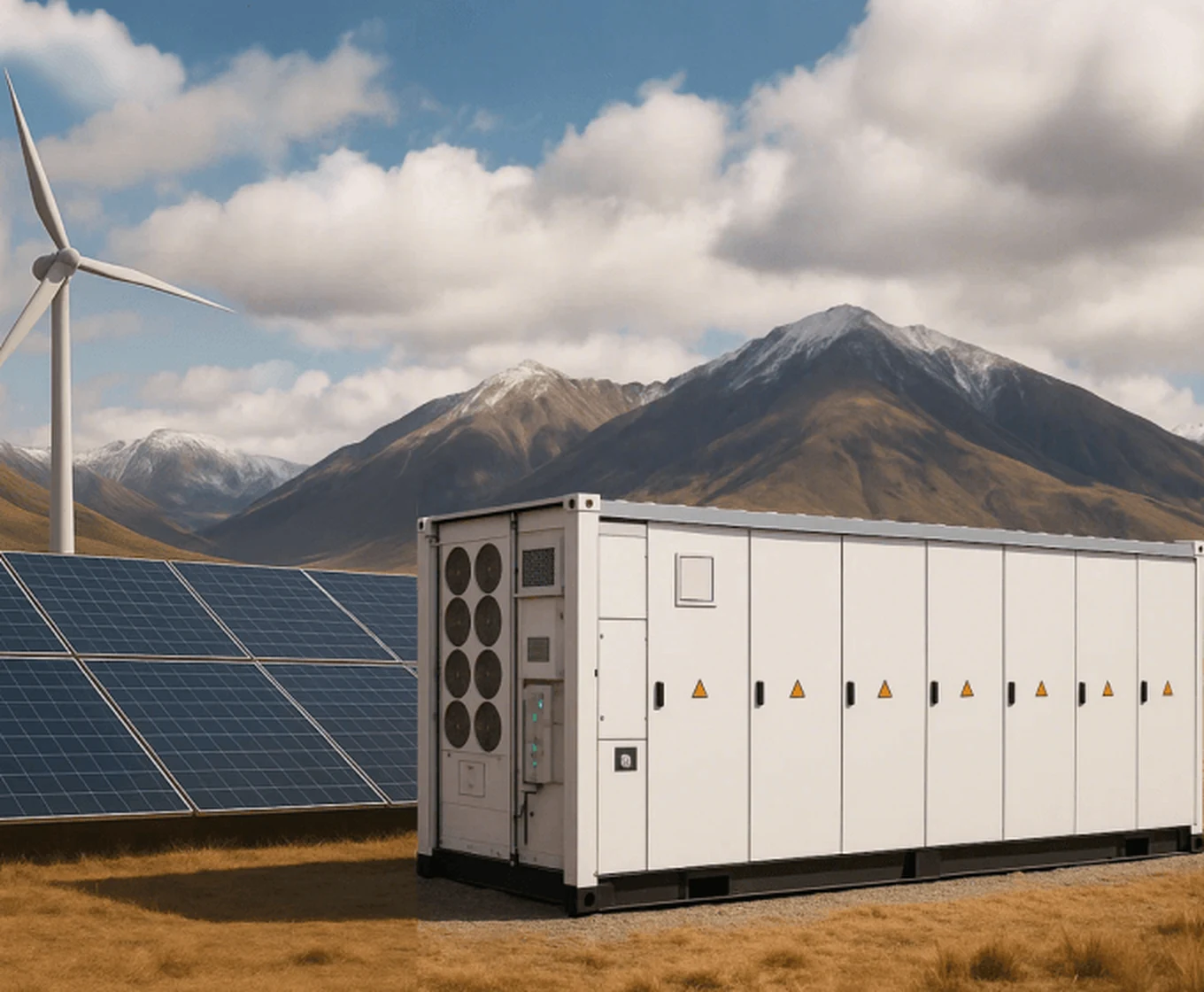
Containerized battery energy storage system installed alongside solar and wind generation
Energy / BESS

Commercial and industrial BESS solutions for Canadian energy infrastructure

MOTIRATECH provides complete Canadian project solutions for battery energy storage — assessment, design, equipment, engineering, installation coordination, system integration, commissioning and O&M for commercial, industrial and infrastructure projects.

Engineering position

Energy storage is an engineering decision made from site data. We size and configure systems around measured load behaviour, existing infrastructure and a defined operating objective — and we say so when storage is not the right answer for the site.

BESS solution overview

What MotiraTech provides

Canadian engineering, qualified manufacturing partners, global sourcing and supply-chain capabilities, North American project delivery, system integration and field support — combined as one project solution.

System configuration

Storage requirements are derived from load behaviour, tariff structure and operating objectives, then translated into a system configuration — energy and power basis, enclosure format and interconnection point.

Integration

Battery system, power conversion and site electrical infrastructure are engineered as one interface, including protection coordination, metering and the physical and thermal installation arrangement.

Controls and EMS

Control strategy is defined with the site: what the system is dispatched for, how it interacts with existing generation and load, and how it is monitored and reported.

Deployment and support

Supply coordination, installation support, commissioning and post-commissioning technical assistance, including remote and field-based support for remote operations.

Complete BESS project capability

Assessment to O&M

MOTIRATECH is not a supply-only importer. The customer receives a Canadian project solution built around facility data, engineering, equipment selection, integration, commissioning and operating support.

01

Assessment

02

Design

03

Equipment

04

Engineering

05

Installation

06

Integration

07

Commissioning

08

O&M

British Columbia / Commercial & industrial BESS

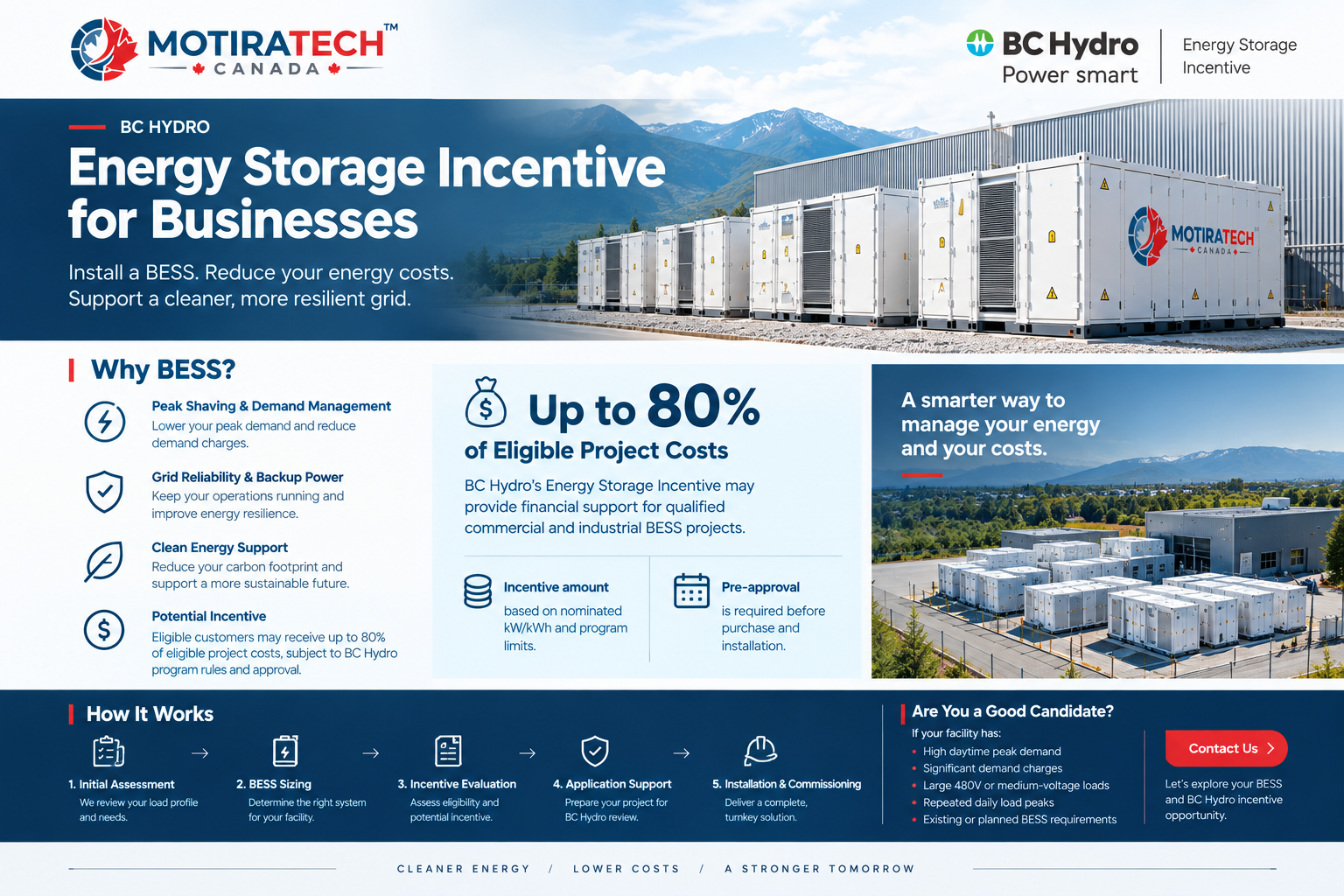
BC Hydro Energy Storage Incentive for Businesses

BC Hydro's Energy Storage Incentive may provide an opportunity for eligible commercial and industrial customers to reduce the upfront cost of installing a battery energy storage system. MotiraTech helps businesses evaluate whether BESS makes sense for their facility from both a technical and financial perspective.

MotiraTech overview of the BC Hydro Energy Storage Incentive for commercial and industrial battery energy storage projects
Where BESS may be used

A properly sized system starts with the facility's actual electricity usage. It may be worth evaluating where a facility has high daytime demand, significant demand charges or recurring peak loads.

  • Peak shaving and demand management
  • Reducing demand-related electricity costs
  • Energy management during high-load periods
  • Backup power and operational resilience
  • Participation in demand flexibility programs
Potential incentive

Up to 80%

of eligible project costs

BC Hydro's Energy Storage Incentive may provide up to 80% of eligible project costs, subject to BC Hydro program eligibility, incentive calculations, project requirements and approval.

Pre-approval is required

Do not purchase or install the system before receiving the required approval. Eligibility and available funding must be confirmed against BC Hydro's current official program documentation. Customers should not assume that every project will receive an 80% incentive; program requirements and availability may change.

Review current BC Hydro business programs
How MotiraTech can help

From facility load data to an application-ready technical basis

We can review the load profile, determine an appropriate BESS size, assess the potential incentive opportunity and help prepare the technical information required for the application.

  1. STEP 01

    Load assessment

    Review the facility's interval usage, recurring peak loads and demand-related electricity costs.

  2. STEP 02

    BESS sizing

    Determine an appropriate power and energy basis from the actual load profile and operating objective.

  3. STEP 03

    Incentive evaluation

    Assess the potential opportunity against current BC Hydro eligibility, technical and program requirements.

  4. STEP 04

    Application support

    Prepare the technical information required for review before any equipment is purchased or installed.

  5. STEP 05

    Installation & commissioning

    Following approval and procurement, coordinate delivery, integration, testing and commissioning.

Does your facility have high demand charges or recurring peak loads?

Send available interval load data and a recent electricity bill. Our engineering team can review the technical basis and the potential BC Hydro incentive pathway with you.

Request a BESS Assessment
Important notice

The information above is provided for general reference only. Incentive amounts, eligibility criteria, capacity limits and program availability are determined solely by BC Hydro and may change at any time. Whether a specific project qualifies — and the actual funding level it may receive — depends on BC Hydro's most current program requirements, technical eligibility rules, and the utility's pre-approval and final approval decisions. MotiraTech does not guarantee incentive qualification, funding amounts or program outcomes for any project. Always confirm current terms directly against BC Hydro's official program documentation before making purchasing or purchasing decisions.

Case study / Richmond, British Columbia

1 MW / 2.088 MWh — peak shaving and demand management for a continuous-production industrial facility

We recently completed a detailed BESS assessment for a continuous-production industrial facility in Richmond, BC, using 19 months of actual 15-minute interval load data. The site has a 480 V three-phase system, approximately 38.6 GWh of annual energy consumption and a recorded peak demand of 7,207 kVA. The customer's target was to manage demand above 6,000 kVA while also protecting an approximately 6.7 MVA service capacity.

19 months
of actual 15-minute interval load data
Facility metering, Jan 2025 – Jul 2026
38.6 GWh
annual energy consumption
Facility metering, Jan 2025 – Jul 2026
7,207 kVA
maximum recorded demand
Facility metering, Jan 2025 – Jul 2026
6.7 MVA
site service capacity to be protected
Facility metering, Jan 2025 – Jul 2026

The challenge

The facility operates as a continuous-production industrial plant with a large and stable electrical load. Historical meter data showed significant demand above the customer's 6,000 kVA target, and the site has an approximately 6.7 MVA contract/service capacity. The goal was to reduce peak utility demand, manage demand charges and protect the site's electrical capacity while maintaining production operations.

The key finding

Based on the actual load profile, our analysis identified that energy capacity — not simply discharge power — was the key factor in the system design. A BESS should not be sized simply by looking at the facility's maximum demand. It should be designed around how the facility actually operates.

Operating pattern before sizingThe load profile requires the BESS to be designed around energy duration, not just maximum power: sustained daytime peaks, a midday production dip that allows supplementary recharging, and overnight recharging at the site's night base load.

Recommended configuration

Sized from 19 months of measured load data

1 MW / 2.088 MWh

01
AC power
1 MW
02
DC capacity
2.088 MWh
03
Configuration
8 × 261 kWh C&I BESS units
04
Connection
480 V, three-phase
05
Application
Behind-the-meter peak shaving
06
Recharging
Overnight and midday recharging
07
Post-peak period
Standby support after the peak-shaving period
Historical simulation

Assessed against the site's own criteria

The recommended configuration was assessed against the facility's measured demand history under the analyzed operating conditions. Coverage results are specific to this load profile and operating strategy and are not published as generic figures.

Contract capacity protection

100% coverage

Historical simulation showed the system could achieve full coverage against the approximately 6.7 MVA service capacity criterion.

6,000 kVA peak-shaving target

54% full coverage

Full coverage of the 6,000 kVA peak-shaving target under the analyzed operating conditions, with the system reducing demand above the target for the remainder of the operating periods.

How we approach industrial BESS

Start with the customer's actual electrical data

This is how we approach industrial BESS projects at MotiraTech: start with the customer's actual electrical data, understand the operating pattern, size the system around the real demand profile, and then develop the electrical and operating strategy.

Load data analysed in this assessment
  • kW and kvar demand
  • Monthly maximum demand
  • Power factor
  • Contract capacity
  • Daily peak duration
  • Charging opportunities
  • Daily discharge energy
  • Battery degradation
  • Long-duration discharge needs
Basis of the figures shown

All figures in this case study are taken from the facility's own 19 months of 15-minute interval metering and from a historical simulation performed on that data. Coverage results depend on the site's load profile, tariff structure and operating strategy and will differ for other facilities. Facility and customer details are not disclosed.

Have a facility with high daytime demand or demand charges?

Send available interval load data and a recent electricity bill. Our engineering team will review the load profile and develop a sizing and operating strategy around how your facility actually operates.

Request a BESS Assessment
System categories

BESS configurations we engineer

Solution categories, not catalogue products. The appropriate configuration follows from the assessed duty, site conditions and interconnection requirements.

Commercial & industrial BESS

Storage configured around a facility or plant load — demand management, load shifting and supporting site power quality objectives.

Containerized BESS

Enclosure-based systems for outdoor, brownfield and remote installations where site civil works and footprint are the deciding constraints.

Liquid-cooled BESS

Systems using liquid thermal management, evaluated where duty cycle, ambient conditions or density requirements make the thermal design the governing factor.

Utility / large-scale BESS

Larger installations connected at distribution or transmission level, where interconnection requirements and utility coordination shape the engineering.

Hybrid energy systems

Storage combined with renewable generation and, where present, existing generator capacity — coordinated through a single control strategy.

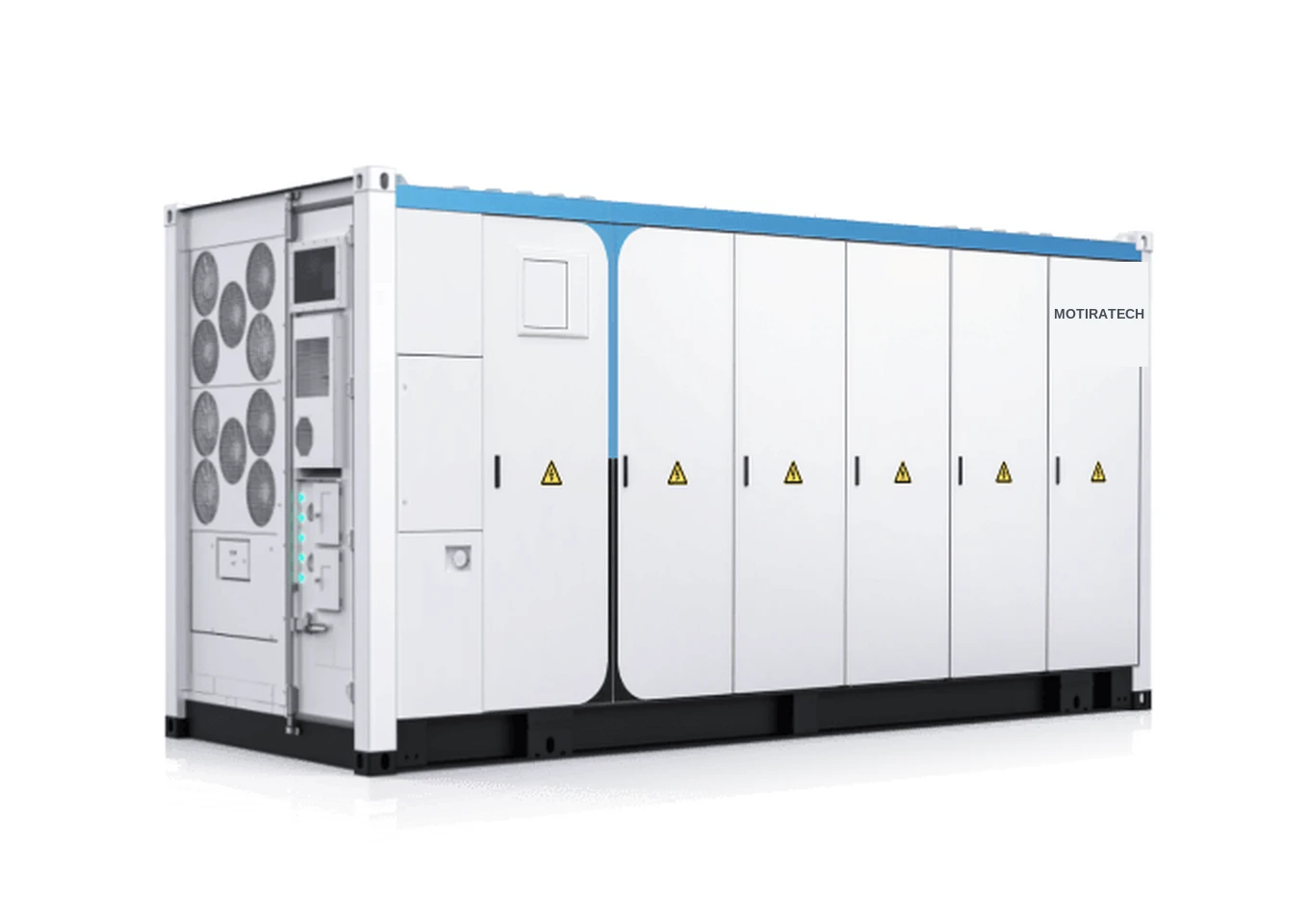
MotiraTech 20 ft containerized battery energy storage system with integrated liquid-cooling units
Containerized battery energy storage system with integrated liquid cooling
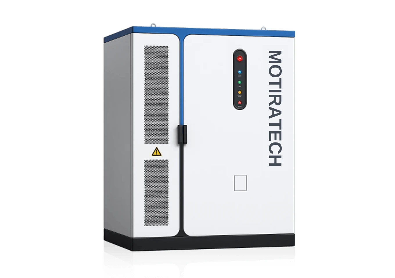
MotiraTech outdoor commercial and industrial energy storage cabinet with status indicators
Outdoor commercial and industrial energy storage cabinet
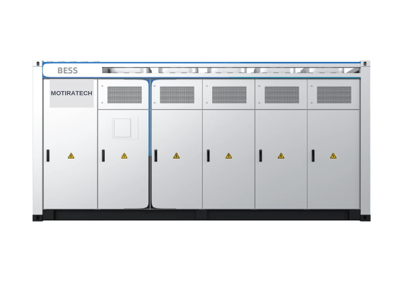
Front elevation of a MotiraTech containerized BESS showing battery and conversion compartments
Front elevation showing battery and conversion compartments
Specifications confirmed per applicationCapacities, power ratings, voltages, cell chemistry, cycle life, thermal performance, efficiency, degradation behaviour, warranties and certifications are confirmed per application against manufacturer documentation, and documented in project-specific technical documentation.
Industrial applications

Where storage is assessed

Each application is evaluated against the site's own load data and operating objective. Outcomes are site-specific and are not published as generic figures.

Peak demand management

Discharging during identified demand peaks so the site's billed demand is shaped by the storage system rather than by short load excursions.

Load shifting

Moving energy consumption between periods where a time-of-use or demand-based tariff makes the timing of consumption commercially relevant.

Backup and resilience

Supporting defined critical loads through supply interruptions, with the supported load list and duration established during assessment.

Renewable integration

Absorbing and re-dispatching variable solar or wind output so generation and site load can be coordinated.

Remote power

Storage for off-grid and remote sites where generation is local, logistics are constrained and fuel handling is a significant operating cost.

Microgrid and hybrid power

Coordinating storage, renewable generation and generators as one system with a defined dispatch and transition strategy.

Industrial energy management

Using storage alongside monitoring and control so energy behaviour becomes a managed part of plant operation rather than a fixed cost.

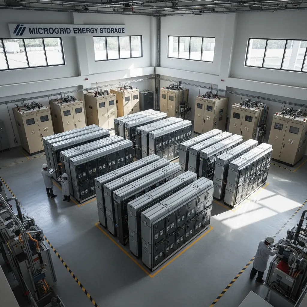
Microgrid and energy storage system installation
Microgrid and energy storage installation
Remote power system for off-grid industrial operations
Storage-based power for off-grid and remote operations
Outcomes are site-specificThe demand, energy-cost, fuel and resilience outcomes of a storage system depend on the site's load profile, tariff structure, generation mix and operating strategy, and are established from site data during application engineering.
BESS product portfolio

Commercial, industrial and utility-scale battery energy storage systems

MotiraTech provides battery energy storage solutions for commercial, industrial and utility-scale applications, combining modular battery systems, power conversion, controls and project-specific integration.

Product data sourceThe specifications below are transcribed from the supplied manufacturer datasheets for the equipment MotiraTech supplies and integrates. Equipment is manufactured by MotiraTech's manufacturing partners; MotiraTech is responsible for engineering, integration and project delivery.
Commercial & industrial energy storage

MotiraTech Commercial Energy Storage System

MotiraTech ES-125 kW / 279.55 kWh · MotiraTech ES-250 kW / 559.1 kWh

Modular C&I energy storage in two configurations — 125 kW / 279.55 kWh and 250 kW / 559.1 kWh — combining a liquid-cooled LFP battery system, an integrated bidirectional PCS and an integrated EMS in a North American 480 Vac configuration.

Applications
  • Peak shaving / demand-charge management
  • Load shifting
  • Self-consumption
  • PV energy shifting
  • Time-of-use optimization
  • Active and reactive power control
  • Zero-export applications
MotiraTech outdoor commercial and industrial energy storage cabinet with status indicators
Outdoor C&I energy storage cabinet
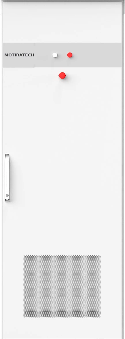
Liquid-cooled LFP battery cabinet for commercial and industrial energy storage
Liquid-cooled LFP battery cabinet (O652280-E)
Integrated bidirectional power conversion cabinet with energy management system
Integrated bidirectional PCS cabinet with EMS
Commercial ESS — key product information11 ROWS
01Configurations125 kW / 279.55 kWh · 250 kW / 559.1 kWh
02ModelsMotiraTech ES-125 kW / 279.55 kWh · MotiraTech ES-250 kW / 559.1 kWh
03Battery chemistryLFP
04CoolingLiquid-cooled battery system
05Power conversionIntegrated bidirectional PCS
06ControlsIntegrated EMS
07ArchitectureModular and scalable
08Nominal grid voltage480Vac
09EnclosureNEMA 3R (PCS and battery cabinets)
10Fire suppressionIntegrated
11ConfigurationNorth American
Manufacturer product certification / compliance
System
  • UL 9540
Battery
  • UL 1973
  • UL 9540A
PCS
  • UL 1741-SA/SB Ed. 3
  • CSA C22.2 No. 107.1-16
  • IEEE 1547a-2014
  • IEEE 1547-2018
  • FCC Part 15

As stated in the supplied manufacturer datasheet. These are product certifications held by the equipment manufacturer, not corporate certifications of MotiraTech.
Utility / large-scale containerized platform

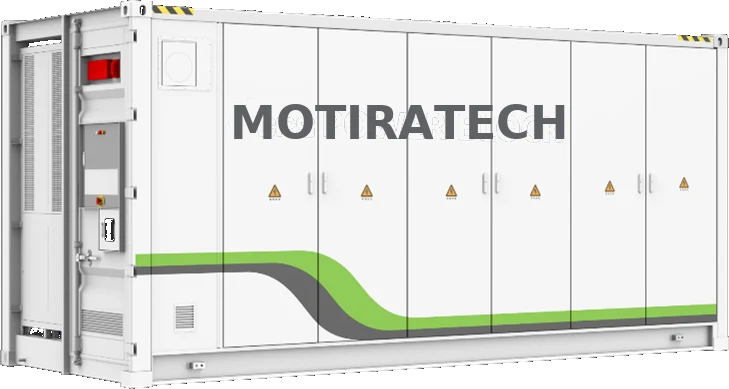
5 MWh Liquid-Cooled Battery Energy Storage System

MotiraTech ES-5015KWH-US-M-R

A 20 ft containerized, liquid-cooled LFP battery platform for utility-scale and large industrial installations, paired with external power conversion for medium-voltage site integration.

Applications
  • Utility-scale BESS
  • Renewable-energy integration
  • Microgrids
  • Industrial energy infrastructure
  • Large commercial and industrial applications
  • Hybrid power systems
5 MWh liquid-cooled containerized battery energy storage system in a 20 ft enclosure
20 ft liquid-cooled containerized battery system
MotiraTech 20 ft containerized battery energy storage system with integrated liquid-cooling units
Container enclosure with integrated liquid-cooling units
Front elevation of a MotiraTech containerized BESS showing battery and conversion compartments
Front elevation — battery and conversion compartments
MotiraTech ES-5015KWH-US-M-R — primary specifications12 ROWS
01Battery capacity5015.9kWh
02Battery chemistryLFP, 314 Ah cells
03Container20ft
04Rated voltage1331.2V
05Operating voltage1164–1497V
06Maximum power2508kW
07CoolingLiquid cooling
08ProtectionIP54
09Fire suppressionIntegrated
10CommunicationRS485 / Ethernet / CAN
11ProtocolsModbus RTU / Modbus TCP / CAN
12Dimensions6058 × 2896 × 2438mm
Manufacturer product certification / compliance
Battery
  • UL 1973
  • UL 9540A
System
  • UL 9540

As stated in the supplied manufacturer datasheet. These are product certifications held by the equipment manufacturer, not corporate certifications of MotiraTech.
Power conversion / utility integration

2 MW / 2.4 MW String PCS Station

MotiraTech PSW2M-US (2000 kW) · MotiraTech PSW2.4M-US (2400 kW)

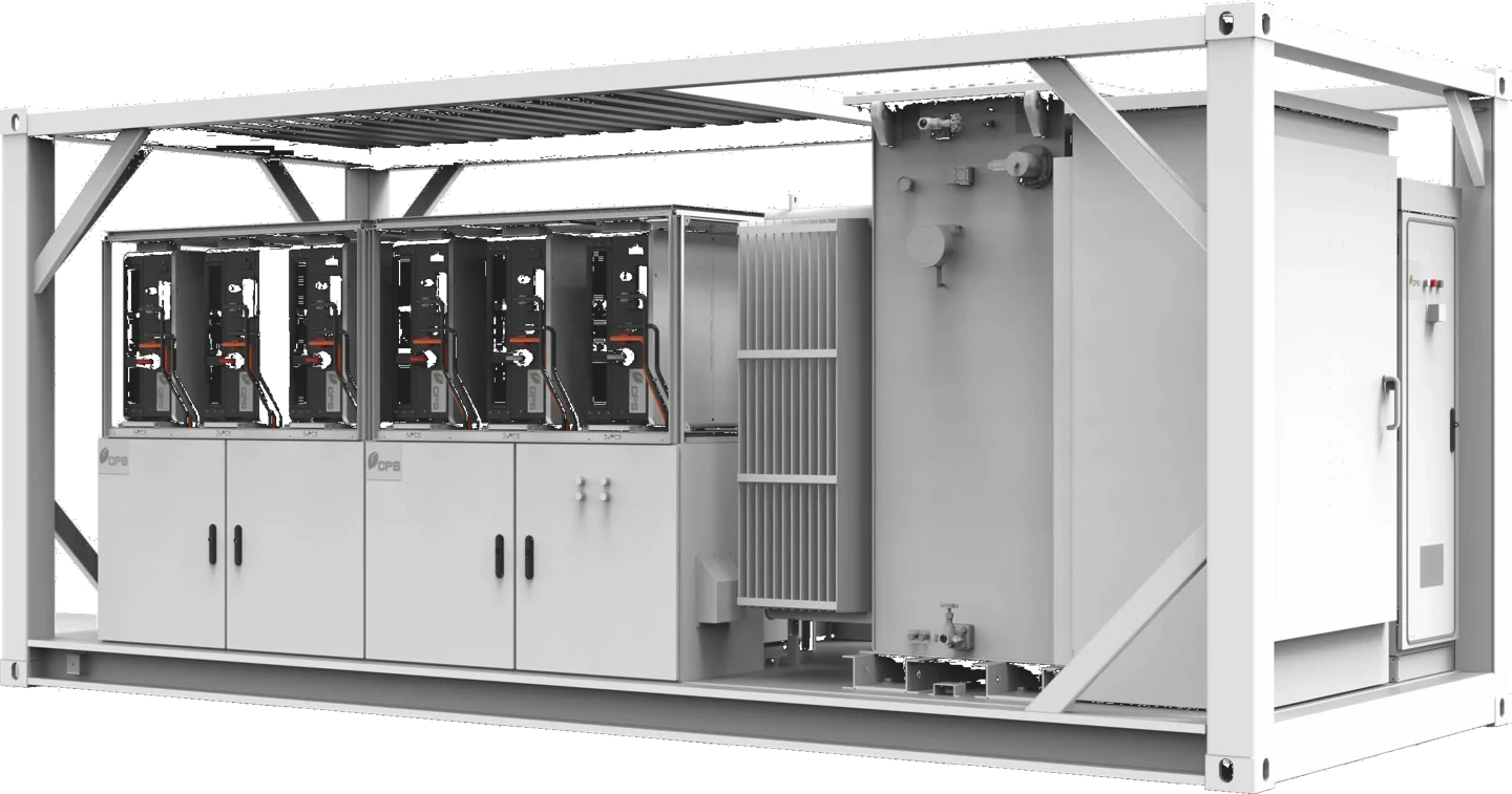
A power conversion station integrating string PCS units, low-voltage BOS, switchgear, auxiliary power, communications and a medium-voltage transformer as one delivered assembly for utility-scale storage interconnection.

Smart-grid functionality
  • Volt Ride-Through
  • Frequency Ride-Through
  • Ramp-rate control
  • Power-factor control
  • Volt-VAR
  • Frequency-Watt
  • Volt-Watt
String PCS station with low-voltage balance of system and medium-voltage transformer on a 20 ft skid
String PCS station with LV BOS, switchgear and MV transformer
String PCS station — key specifications08 ROWS
01ModelsMotiraTech PSW2M-US (2000 kW) · MotiraTech PSW2.4M-US (2400 kW)
02DC input1500 V maximum
03Nominal-power DC range950–1500V
04Grid frequency60Hz
05Medium voltage34.5kV
06EnclosureNEMA 3R
07CommunicationRS485 / Ethernet / CAN
08Integrated equipmentString PCS, LV BOS, switchgear, auxiliary power, communications, MV transformer
Manufacturer product certification / compliance
Converter
  • UL 1741
  • CSA C22.2 No. 107.1-16
Interconnection
  • IEEE 1547-2018
Emissions
  • FCC Part 15

As stated in the supplied manufacturer datasheet. These are product certifications held by the equipment manufacturer, not corporate certifications of MotiraTech.
Mobile hybrid microgrid

Hybrid Solar–Storage–Diesel Microgrid System

MotiraTech E42S24G25P2/27-NA · 24 kW / 42 kWh / 18 kW generator

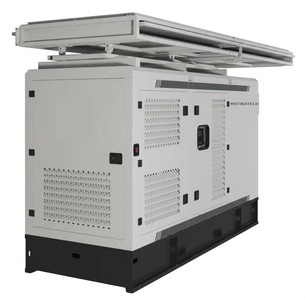
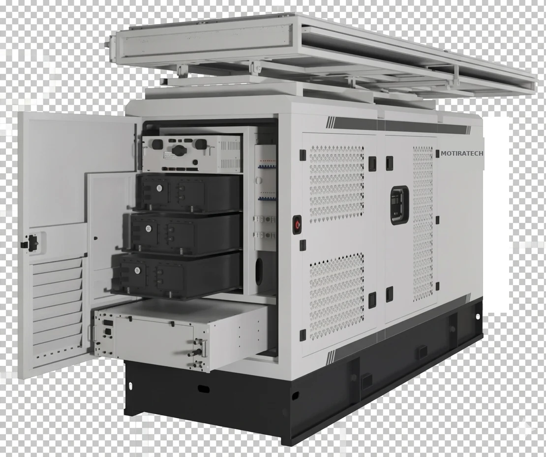
A trailer-ready hybrid microgrid combining a 42 kWh liquid-cooled LFP battery, a 24 kW hybrid inverter with EMS, onboard solar expandable to 27 kW and an 18 kW diesel generator as backup. Designed for cold-climate, off-grid and temporary power where diesel-only generation is costly to supply.

System characteristics
  • Operating range −30 °C to +55 °C with liquid thermal management
  • Trailer-ready at 1.7 t for rapid redeployment
  • Auto-unfolding onboard solar, expandable via plug-in MPPT ports
  • Hybrid EMS with on/off-grid switching, UPS function and remote monitoring
Applications
  • Remote and Indigenous community microgrids
  • Mining, forestry and construction camps
  • Emergency and disaster-response power
  • Off-grid lodges, research stations and parks
  • Grid-weak rural electrification
  • Seasonal agricultural operations
Mobile hybrid solar, battery storage and diesel microgrid unit with auto-unfolding solar array
Mobile hybrid unit with auto-unfolding solar array deployed
Hybrid microgrid unit with cabinet door open showing battery modules and control gear
Battery modules and control gear
Front view of the hybrid microgrid unit showing hybrid inverter, battery and diesel generator compartments
Inverter, battery and generator compartments
Hybrid microgrid system — key specifications25 ROWS
01ModelMotiraTech E42S24G25P2/27-NA
02System rating24 kW / 42 kWh / 18 kW generator
03Battery42 kWh LFP (automotive-grade)
04Cycle life≥ 4,000 cycles @ 80% DOD, 25 °C
05Battery thermal managementLiquid-cooled and heated
06Depth of discharge90%
07Battery temperature range−20 °C to +60 °C
08Inverter / PCS24 kW hybrid, 120/240 V @ 60 Hz
09Inverter efficiency96.4% CEC
10Inverter protectionIP65
11THDi< 2%
12Onboard solar2 kW (3 × N-type panels), 23.3% panel efficiency
13Solar expansionUp to 27 kW via 3 × 9 kW MPPT
14PV inputs4 × MPPT (150–430 V)
15Tilt angle0 / 15 / 30 / 45°, manual
16GeneratorCummins 25 kW engine / 18 kW generator, 120/240 V @ 60 Hz
17Fuel tank180L
18Fuel consumption6.1 L/h @ 100% load
19Altitude rating≤ 4,500m
20Noise level75 dB(A) @ 7 m
21Dimensions (W × D × H)3,530 × 1,130 × 1,880mm
22Weight1.7 t (trailer-ready)
23Operating temperature−30 °C to +55 °C
24Protection gradeIP54, C5 corrosion resistant
25EnclosureSilencer-equipped, all-weather
Manufacturer product certification / compliance
Battery / system
  • UL 1973
  • UL 9540
  • UL 9540A
Power conversion
  • UL 1741
Cell / transport / EMC
  • CSA C22.2 No. 62133
  • UN 38.3
  • FCC Part 15

As stated in the supplied manufacturer datasheet. These are product certifications held by the equipment manufacturer, not corporate certifications of MotiraTech.
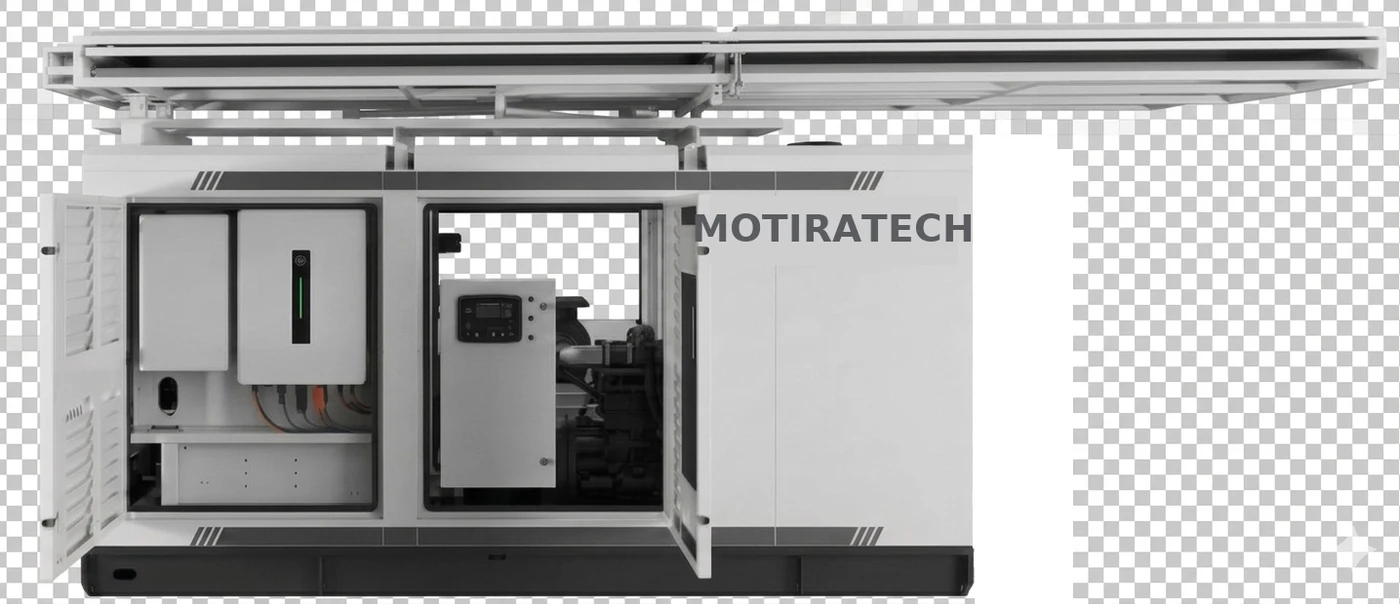
Solar yield, generator runtime and diesel displacement depend on site irradiance, load profile and operating strategy, and are established from site data during application engineering.

System relationship

How the products fit together

The portfolio is a single system chain, not a catalogue. Battery system, power conversion, medium-voltage interface and site electrical system are configured together for the application.

Utility / large-scale configuration
Battery system
5 MWh liquid-cooled BESS (MotiraTech ES-5015KWH-US-M-R)
Power conversion
2 MW / 2.4 MW string PCS station (MotiraTech PSW2M-US / PSW2.4M-US)
Medium-voltage / site integration
Switchgear, transformer, protection and metering
Grid / industrial load / renewable generation
Commercial & industrial configuration
Battery cabinets
279.55 kWh / 559.1 kWh liquid-cooled LFP battery cabinets
Integrated bidirectional PCS + EMS
125 kW / 250 kW, NEMA 3R
480 V site electrical system
Facility distribution, PV and site load

Both configurations map onto the same system architecture shown below: battery system, power conversion, controls, site distribution and the grid, load and generation it serves.

MotiraTech role

What MotiraTech does with these systems

Product supply is one part of the work. The engineering that makes the equipment fit the site is the deliverable.

Application assessment

Review of load behaviour, tariff structure, generation mix and site constraints to establish what the storage system has to do.

System sizing and configuration

Energy and power basis matched to the assessed duty, then mapped onto the available product configurations.

Equipment selection

Selection between C&I cabinet systems and containerized platforms, and the matching power-conversion arrangement.

Electrical and system integration

Interconnection point, protection coordination, metering, medium-voltage interface and physical installation arrangement.

EMS and control requirements

Dispatch strategy, interfaces to existing SCADA, PLC or plant control systems, and monitoring and reporting requirements.

Site-interface definition

Footprint, civil and thermal interfaces, cable routing, access and safety requirements defined against the selected equipment.

Project coordination

Supply, documentation, schedule and scope-boundary coordination between the manufacturer, site and installing parties.

Commissioning support

Energisation support, functional and control-strategy testing, settings verification and operator familiarisation.

Field support

Post-commissioning technical support, spares planning and remote or on-site assistance.

System architecture

How the system fits together

The battery system connects through the power conversion system to site distribution, where the grid, site load and any renewable generation or generator capacity meet. The EMS coordinates dispatch across them.

BESS system architecture — schematic relationships
Battery systemcells, racks, BMSPCSpower conversionSite distributionAC bus / switchgearUtility gridwhere connectedSite loadprocess / facilityRenewable generationwhere presentGeneratorwhere applicableEMS / controlsdispatch, monitoring, site coordinationDashed elements are application-dependent andconfirmed per site during assessment.
Topology schematic. Actual configuration, protection, metering and interconnection arrangements are defined per application. No ratings, capacities or performance values are represented.
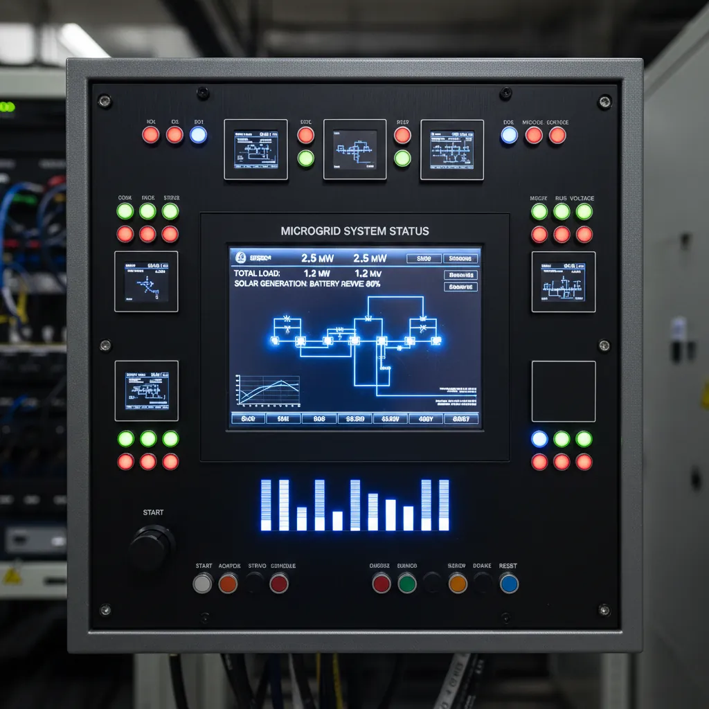
Microgrid control panel with live monitoring displays
Microgrid control panel with live system monitoring
Energy monitoring and performance dashboard
Energy monitoring and dispatch dashboard
Core system elements
  • Battery system — cells, racks, battery management and the enclosure or building housing them.
  • PCS — power conversion between the battery DC system and the site AC distribution, with its protection and control interfaces.
  • EMS — dispatch logic, monitoring and coordination with site metering and the plant control system.
Site interfaces
  • Grid / load — the interconnection point, protection coordination and the facility loads the system serves.
  • Renewable generation — solar, wind or other on-site generation, where present.
  • Generator — where applicable, existing generation retained within a hybrid or off-grid arrangement.
Engineering & integration

MotiraTech's engineering role

An engineering-led scope, not a supply-only transaction. The same team carries the application from assessment through commissioning and support.

Application assessment

Review of load data, tariff structure, existing electrical infrastructure and site conditions to establish whether storage is technically and commercially appropriate.

System sizing

Energy and power basis derived from measured load behaviour and the intended duty, rather than from a catalogue selection.

Configuration

Enclosure format, thermal management approach, layout, interconnection point and protection philosophy defined for the site.

Integration

Coordination of the battery system, PCS and site distribution, including metering, protection settings and physical installation interfaces.

Controls / EMS coordination

Dispatch logic and interfaces to existing SCADA, PLC or building/plant control systems, agreed with the site's controls owner.

Commissioning

Energisation, functional testing against the agreed control strategy, operator familiarisation and handover documentation.

Field support

Post-commissioning technical support, spares planning and remote or on-site assistance, including support for remote operations.

Application data

Information required to evaluate a storage application

Send what is available. A first technical position can usually be formed from load data, the tariff basis and the site's electrical arrangement; the remainder is needed before a firm scope or quotation.

01
Site & operation
Location, grid-connected or off-grid, facility type and operating hours.
02
Load data
Interval load data where available, peak and average demand, and load profile variation.
03
Objective
Demand management, resilience, renewable integration, fuel reduction or a combination.
04
Electrical infrastructure
Service voltage, incoming capacity, switchgear arrangement and available connection points.
05
Existing generation
Solar, wind, generator or other on-site generation, with ratings and current control arrangement.
06
Tariff / energy cost basis
Utility rate structure, demand charges or diesel/fuel cost basis for off-grid sites.
07
Critical loads
Loads that must be supported through an interruption, and for how long.
08
Controls environment
Existing SCADA, PLC or plant control system, protocols and monitoring expectations.
09
Site conditions
Available footprint, indoor/outdoor, ambient range, altitude, access and fire/safety requirements.
10
Project basis
New build or existing facility, target schedule, permitting status and support expectations.

Have interval load data or a single-line drawing?

Our engineering team will review the data and respond with a technical position on suitability, configuration and scope.

Send application details
Project delivery

Assessment to field support

A representative delivery sequence. Scope and stage boundaries are confirmed per project — not every project runs every stage, and some run in parallel.

  1. STEP 01

    Assessment

    Load, tariff, infrastructure and site review to confirm the storage case and the constraints it must work within.

  2. STEP 02

    System design

    Energy and power basis, operating strategy and single-line concept developed against the assessed duty.

  3. STEP 03

    Configuration

    Enclosure format, thermal approach, layout and interconnection defined; scope boundaries confirmed with the project team.

  4. STEP 04

    Engineering

    Detailed electrical, mechanical and controls engineering, interface documentation and protection coordination.

  5. STEP 05

    Manufacturing / supply

    Supply coordination, factory testing and documentation control through to delivery at site.

  6. STEP 06

    Integration

    Installation support and connection into site distribution, protection, metering and the control system.

  7. STEP 07

    Commissioning

    Functional and control-strategy testing, settings verification, operator familiarisation and handover.

  8. STEP 08

    Field support

    Ongoing technical support, monitoring assistance, spares planning and field intervention where required.


Typically within MotiraTech scope
  • Application assessment and storage feasibility review
  • System sizing and configuration against measured site duty
  • Battery system, PCS and EMS specification and integration engineering
  • Interconnection, protection and controls interface definition
  • Manufacturing and supply coordination for the storage package
  • Installation support, commissioning and control-strategy setup
  • Documentation, spares planning and ongoing technical and field support
Typically outside scope unless separately agreed
  • Civil works, foundations and site construction
  • Site electrical installation labour and cable pulling
  • Utility interconnection applications and statutory permitting
  • Plant process design and equipment supply beyond the storage package
Flexible project delivery

Equipment, turnkey EPC and selected energy-service pathways

Delivery structure is selected project by project. MOTIRATECH can provide equipment supply, turnkey EPC coordination, or evaluate selected energy-service structures through affiliated or third-party project entities.

Equipment Supply

BESS equipment and integrated energy storage solutions selected against the facility duty, interconnection point, operating strategy and project documentation.

Turnkey EPC

Engineering, equipment supply, system integration, installation coordination and commissioning support delivered as a coordinated project scope.

Energy Service Solutions

Selected projects may be evaluated for alternative commercial or energy-service structures through affiliated or third-party project entities.

Commercial structures are project-specificMOTIRATECH does not publish guaranteed financing, guaranteed savings, guaranteed returns or fixed-return offers on this site. Any alternative commercial structure requires separate project review and documentation.
Safety & compliance

Configured for the project and jurisdiction

Energy storage systems are selected and configured according to applicable project and jurisdictional requirements. Certification, permitting and interconnection requirements are confirmed for the specific system and site.

Canadian electrical requirements

Applicable CSA / UL standards

Fire and building requirements

Utility interconnection requirements

Local permitting requirements

Applicable energy storage safety standards

No blanket certification claimEquipment models, system ratings, fire protection approach, electrical design, utility interconnection and local permitting requirements are confirmed against current manufacturer documentation and the authority having jurisdiction for each project.
B2B project inquiry

Request a BESS assessment

A useful storage review starts with facility data: utility, load profile, peak demand, site voltage, existing generation, resilience objective and project schedule.

The form does not promise a subsidy amount. BC Hydro eligibility, incentive calculations and approval are reviewed separately against current program rules.

Request a BESS assessment

Share the available facility and utility information. The assessment starts with real electrical data, not a generic battery size.

The form records the selected file name only. The team can request recent bills or interval-load files by reply email.

Include objectives such as peak shaving, demand flexibility, resilience, EMS integration or commissioning support.

Incentive eligibility and BESS sizing are reviewed from project data and current utility requirements. No incentive amount is assumed or guaranteed.

Technical information

Application-specific documentation

Manufacturer datasheets for the product portfolio are available on request, together with application-specific documentation issued during technical review.

Datasheet

Commercial ESS — 125 kW / 279.55 kWh & 250 kW / 559.1 kWh

MotiraTech Commercial Energy Storage System

Request datasheet
Datasheet

5 MWh Liquid-Cooled Battery Energy Storage System

MotiraTech ES-5015KWH-US-M-R

Request datasheet
Datasheet

2 MW / 2.4 MW String PCS Station

MotiraTech PSW2M-US / MotiraTech PSW2.4M-US

Request datasheet
Downloadable documents pending publicationDirect PDF downloads are not yet published on the site. Until the document library is in place, manufacturer datasheets are issued on request.

Request BESS technical information

Tell us the application and we will issue the relevant technical documentation for the configuration being evaluated.

Request technical information
Applications

Where industrial energy storage is applied

Storage is specified against a problem, not a product category. These pages describe the two applications that account for most industrial enquiries.

Peak demand management

How behind-the-meter storage acts on demand charges, and what an assessment requires.

Peak shaving and load shifting

Remote industrial power

Storage integrated with generation where fuel logistics and generator runtime set the cost of power.

Off-grid and hybrid systems

Integration and commissioning

Electrical integration, installation support and commissioning for energy storage equipment.

Field engineering

MotiraTech ES-125

Liquid-cooled C&I system with integrated PCS and EMS, 480 Vac, NEMA 3R.

125 kW / 279.55 kWh

MotiraTech ES-250

The higher-power configuration of the same modular C&I platform.

250 kW / 559.1 kWh

Industrial demand charges explained

How billed demand is determined and where storage can act on it.

Technical article

Mining operations

Energy storage at processing plants, mine infrastructure and remote sites.

Industry
BESS

Evaluate energy storage for your site

Send your load data and operating objective. We will tell you what a storage system would need to do — and whether it is the right answer for the site.